Manifold pressure gauge, Propeller rpm gauge, Engine indication and crew alerting system – Garmin G1000 Piper PA-46 Matrix User Manual
Page 103
190-01108-00 Rev. B
Garmin G1000 Pilot’s Guide for the Piper PA-46 Mirage/Matrix
89
ENGINE INDICATION AND CREW ALERTING SYSTEM
SY
STEM
O
VER
VIEW
FLIGHT
INSTRUMENTS
EICAS
AUDIO P
ANEL
& CNS
FLIGHT
MANA
GEMENT
HAZARD
AV
OID
ANCE
AFCS
ADDITIONAL
FEA
TURES
APPENDICES
INDEX
EIS information is presented using gauges, horizontal and vertical bar indicators, slide bars, and digital readouts.
Green ranges on the instrument scales indicate normal ranges of operation; yellow and red bands indicate caution
and warning, respectively. During normal operating conditions, an instrument’s title appears in white and the
readout text is green. When a potentially unsafe operating condition occurs, the title and readout color change
to yellow or flash red, indicating a caution or warning. A Master Warning or Master Caution may also be issued.
If the sensor data for a parameter becomes invalid or unavailable, a red “X” is displayed across the indicator and/
or readout.
MANIFOLD PRESSURE GAUGE
NOTE:
Refer to the Pilot’s Operating Handbook (POH) for engine operating limitations.
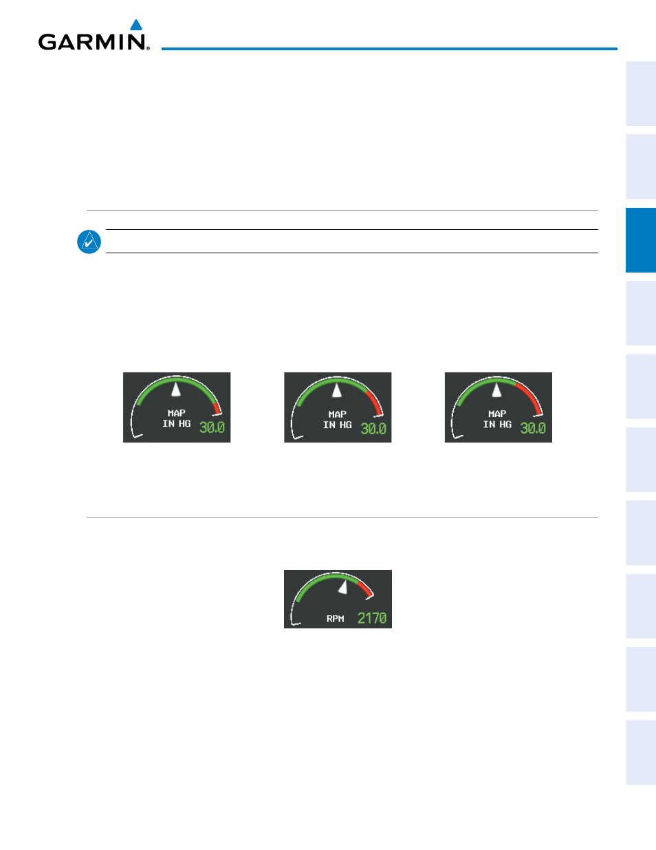
Engine power is displayed in inches of mercury (in Hg) on the manifold pressure (MAP) gauge (Figure 3-5).
The red arc indicates maximum manifold pressure. When ascending through 20,600’ MSL, the red arc range
expands in relation to the current pressure altitude. When descending the red arc contracts until descending
below 20,600’ MSL, at which point the red arc range remains constant.
If manifold pressure exceeds the maximum safe operating range, a warning is issued.
Figure 3-5 Manifold Pressure Gauge and Red Arc Expansion
Below 20,600’ MSL
23,000’ MSL
25,000’ MSL
PROPELLER RPM GAUGE
Propeller speed is shown in revolutions per minute (rpm) (Figure 3-6), and is located below the MAP
gauge. If a propeller overspeed occurs a warning is issued.
Figure 3-6 Propeller RPM Gauge