Panasonic MN103001G/F01K User Manual
Page 460
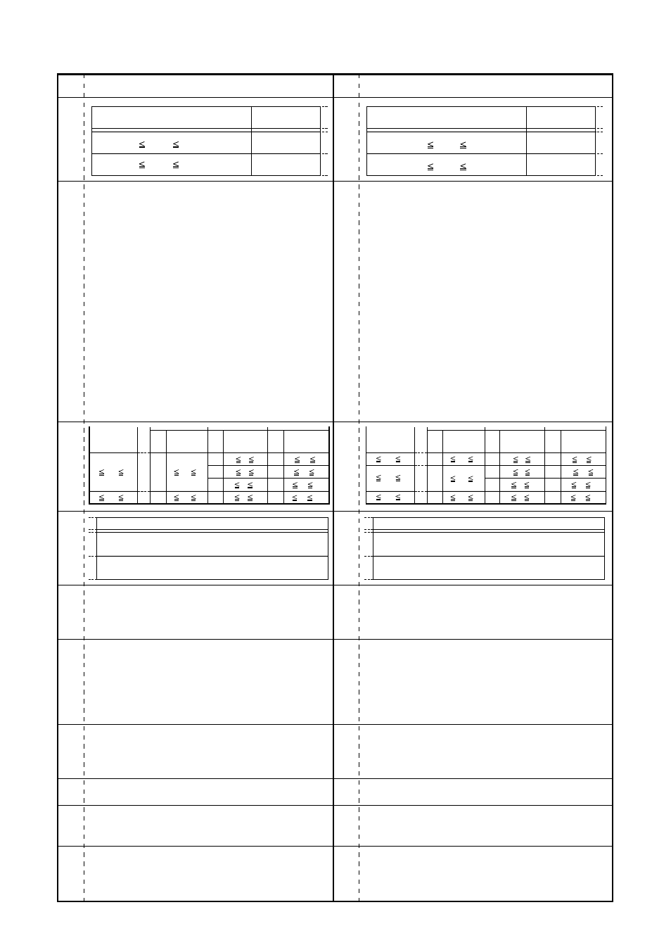
Errors
Page
Corrections
Page
- iv -
P.6-3
P.6-3
P.6-4
P.8-5
P.8-11,
P.8-15
P.8-15,
P.8-20
P.8-35
P.8-35
P.8-36
P.8-41
P.6-3
P.6-3
P.6-4
P.8-5
P.8-11,
P.8-15
P.8-15,
P.8-20
P.8-35
P.8-35
P.8-36
P.8-41
When the reset state is released, SYSCLK, MCLK, and IOCLK are
supplied starting after a certain oscillation stabilization wait time.
Note: For details on the oscillation stabilization wait time, refer to
Chapter 12, “Watchdog Timer.”
Note 1: When a clock is supplied from external, input the clock to the
OSCI pin, and leave the OSCO pin open.
Note 2: The in-circuit emulator (ICE) cannot operate with self-excited
oscillators in the microcontroller. Use the clock generated in the
target system.
When the clock is generated in the target system, supply the
clock to the in-circuit emulator main unit through a buffer with
adequate drive capability. The in-circuit emulator will not operate
correctly if the amplitude of the clock is inadequate, the clock
signal is noisy, or the buffer has inadequate drive capability.
(Following note is added under the table of "When Using DRAM")
Note: When performing ICE trace/emulation in software page
mode, set the CAS parameter to a value of “5” or higher.
(The Setting conditions of EA1 to 0 bit in the table of "When Using
handshaking mode")
00:
prohibited
01:
1MCLK
10:
2MCLK
11:
3MCLK
(Following sentence is added to 13th line.)
_____
The DK signal connected to the microcontroller should be input so
as to be asserted from point EA+DW onward, and is negated before
the next access.
____
(In figure 8-13-4, the DK signal asserted by the read access was
changed so as to be negated before the write access. )
____
(In figure 8-13-5 and 8-13-6, the DK signal asserted by the read
access was changed so as to be negated before the write access.
____
____
Moreover, the signal name, CSn was changed to CS2. )
(Following sentence is added to 20th line.)
_____
The DK signal connected to the microcontroller should be input so
as to be asserted from point EA+DW onward, and is negated before
the next access.
When the reset state is released, SYSCLK, MCLK, and IOCLK are
supplied starting after a certain oscillation stabilization wait time.
Note: • When a clock is supplied from external, input the clock to
the OSCI pin, and leave the OSCO pin open.
• For details on the oscillation stabilization wait time, refer to
Chapter 12, “Watchdog Timer.”
(The Setting condition of EA1 to 0 bit in the table of "When Using
handshaking mode")
00:
0MCLK
~
~
11:
3MCLK
8 fosci 15 MHz
Input frequency range
PLL
When using
When not using
8 fosci 30 MHz
8 MHz fosci 18 MHz
Input frequency range
PLL
When using
8 MHz fosci 20 MHz
When not using
8 fosci 15
8 fsys 15
Multiple
fosci(MHz)
fsys(MHz)
fc (MHz)
fio (MHz)
Multiple
Frequency
Frequency
Frequency
Multiple
32 fc 60*
8 fio 15
8 fosci 30
4 fsys 15
4 fc 15
1 fio 3.75
1/2
1/2
1/8
8 fc 15
2 fio 3.75
1
1
1/4
16 fc 30
4 fio 7.5
2
1/2
4
1
8 fsys 18
Multiple
fosci(MHz)
fsys(MHz)
fc (MHz)
fio (MHz)
Multiple
Frequency
Frequency
Frequency
Multiple
32 fc 60 *
8 fio 15
4 fsys 10
4 fc 10
1 fio 2.5
1/2
1/2
1/8
8 fc 18
2 fio 4.5
1
1
1/4
16 fc 36
4 fio 9
2
1/2
4
1
8 fsys 15
1
8 fosci 20
8 fosci 18
8 fosci 15
Function
Oscillator input pin (when using PLL: 8MHz to 15MHz; when
not using PLL: 8MHz to 30MHz)
Oscillator output pin (when using PLL: 8MHz to 15MHz; when
not using PLL: 8MHz to 30MHz)
Function
Oscillator input pin (when using PLL: 8 MHz to 18 MHz; when
not using PLL: 8 MHz to 20 MHz)
Oscillator output pin (when using PLL: 8 MHz to 18 MHz; when
not using PLL: 8 MHz to 20 MHz)