3 block diagram, Watchdog timer, Fig. 12-3-1 block diagram – Panasonic MN103001G/F01K User Manual
Page 295
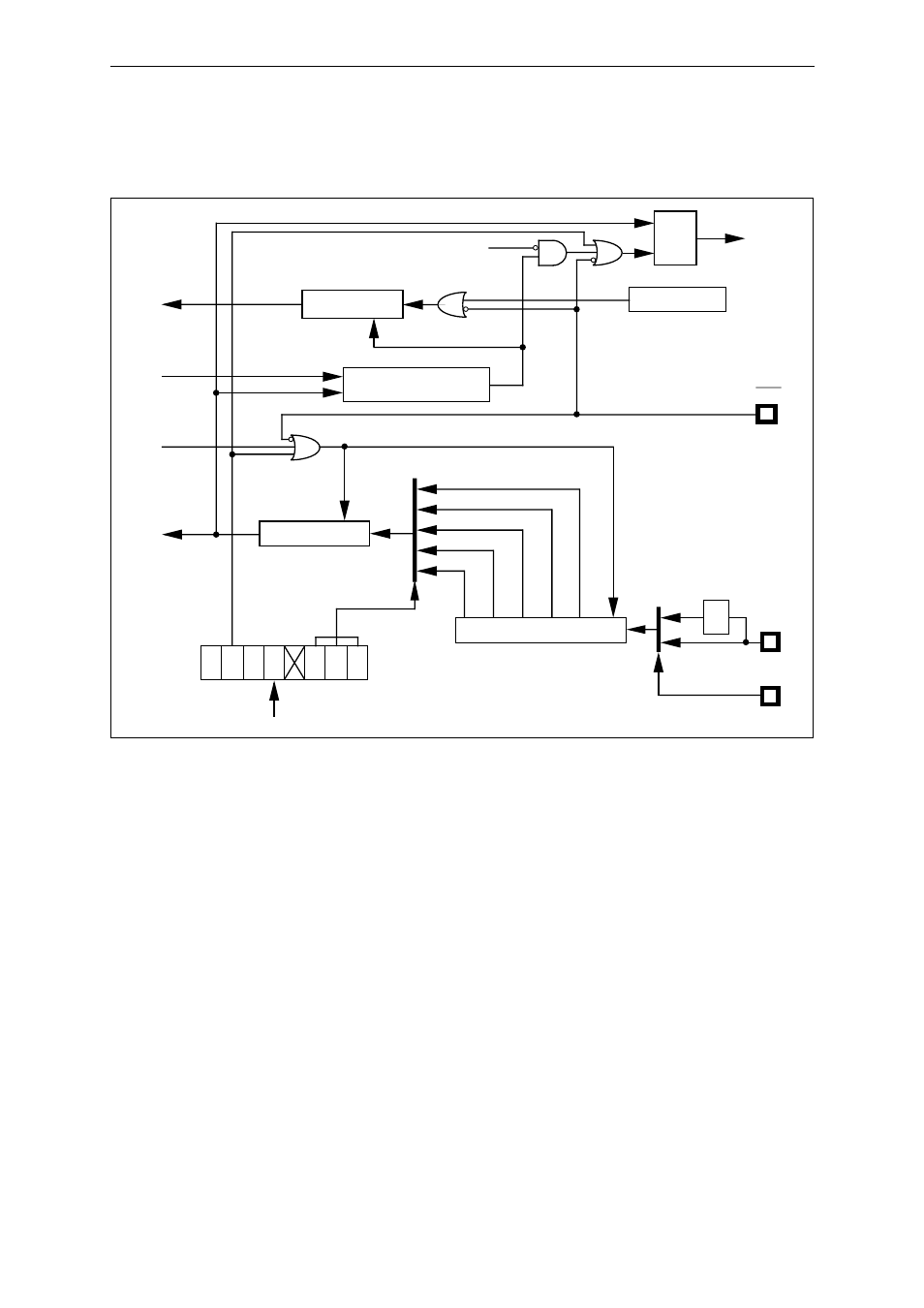
Watchdog Timer
12-3
OSCI
RST
wdovf
S
Q
R
Level output/Pulse output selection
Oscillation
stabilization
wait release,
interrupt
request
Reset
1/2
8
1/2
10
1/2
12
1/2
14
1/2
16
STOP mode
WDBC
WDCTR
CKSEL
L
H
CKSEL input
“H” : PLL is using
“L” : PLL is not using
Clock source
selection
SYSCLK
Internal reset
generation
Internal reset
signal
1/2
8-bit binary counter
16-bit binary counter
RSTCTR register
CK0
Reset
Reset
SYSCLK
8-bit binary counter
wdovf
CK1
CK2
OVF
OVT
RST
CNE
12.3 Block Diagram
Fig. 12-3-1 Block Diagram