3 pin configurations – Panasonic MN103001G/F01K User Manual
Page 380
I/O Ports
15-14
15.3.3 Pin Configurations
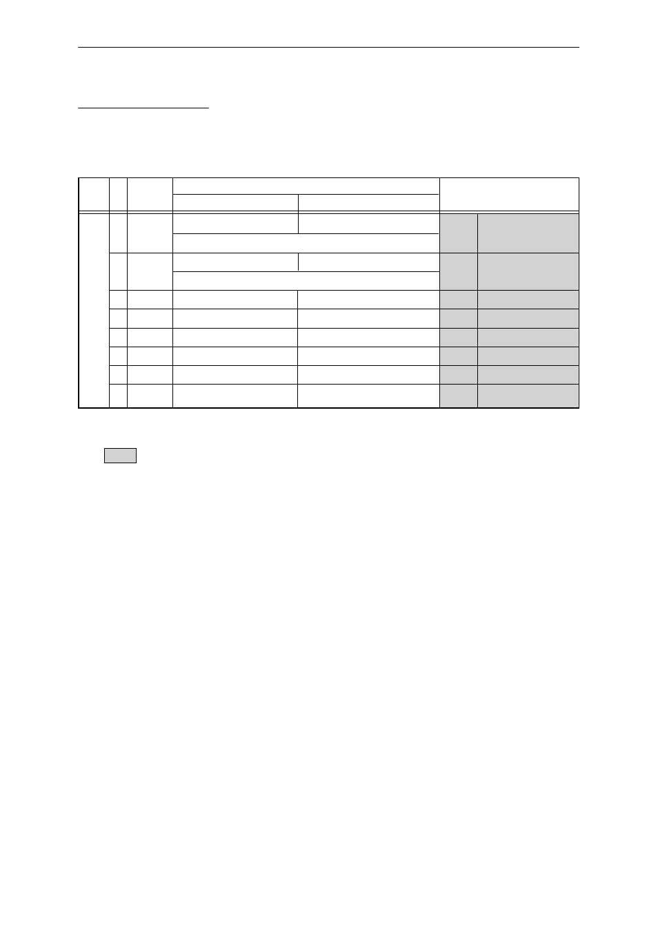
Table 15-3-1 shows the pin configurations for port 1.
Table 15-3-1 Port 1 Configuration
Port
Pin
P1n
P1M = "1"
P1M = "0"
No.
P1nD = "1"
P1nD = "0"
Port 1 96
P10
General-purpose output port
General-purpose input port
D0 *
1
Data input/output
<
<
>95
P11
General-purpose output port
General-purpose input port
D1 *
1
Data input/output
<
<
94
P12
General-purpose output port
General-purpose input port
D2 *
1
Data input/output
93
P13
General-purpose output port
General-purpose input port
D3 *
1
Data input/output
91
P14
General-purpose output port
General-purpose input port
D4 *
1
Data input/output
90
P15
General-purpose output port
General-purpose input port
D5 *
1
Data input/output
89
P16
General-purpose output port
General-purpose input port
D6 *
1
Data input/output
88
P17
General-purpose output port
General-purpose input port
D7 *
1
Data input/output
[Note 1]
: When reset (in address/data separate mode)
"General-purpose input port" is selected
in address/data multiplex mode
. pin No. 95 and 96,
however, are set as RWSEL and AS, respectively.
*1
: In the event of a reset
in address/data separate mode
, the P1PU bit in the P1MD register is set
to "1" and the data pins (the 8 bits D[7:0]) are pulled up.
<<>>
: These pins are set
in address/data multiplex mode
.
Setting invalid:
In address/data multiplex mode
, pin No. 95 is used only for RWSEL, and pin No. 96 is used
only for AS; the P1MD and P1DIR settings are invalid.
[Note 2]
Setting P1M to "0"
in address/data multiplex
mode is prohibited.
[Note 3]
When the bus authority is granted, D7 to D0, AS, and RWSEL go to high impedance.