3 block diagram, 3 11.3 block diagram, Bit timers – Panasonic MN103001G/F01K User Manual
Page 257
16-bit Timers
11-3
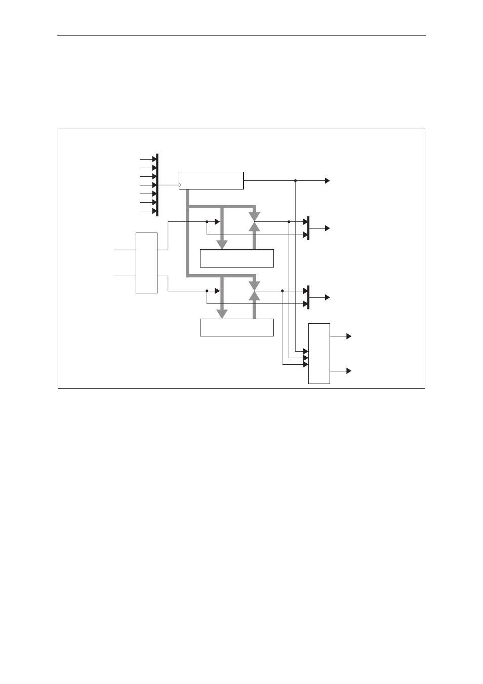
11.3 Block Diagram
Fig. 11-3-1 shows the block diagram for timer 10, and Fig. 11-3-2 shows the block diagram for timers 11
to 13.
Fig. 11-3-1
16-bit Timer Block Diagram (Timer 10)
Timer 10
TM10CA
TM10BC
Compare/capture A register
Binary counter
TM10CB
Compare/capture B register
Pin input control
TM10IRQ
Overflow interrupt
TM10AIRQ
Compare/capture interrupt A
TM10INA
TM10INB
TM10IN0
TM10IN1
TM10IN2
TM10IN5
TM10IN6
TM10IN7
TM10IN4
TM10BIRQ
Compare/capture interrupt B
TM10OUTA
TM10OUTB
Capture
Capture
Match
Match
Pin output control