9 port 7, 1 block diagram, I/o ports – Panasonic MN103001G/F01K User Manual
Page 407
I/O Ports
15-41
15.9 Port 7
15.9.1 Block Diagram
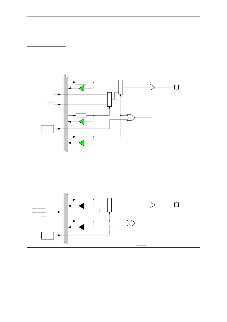
Fig. 15-9-1 and Fig. 15-9-2 show block diagrams for port 7.
Fig. 15-9-1 Port 7 Block Diagram (P73)
Fig. 15-9-2 Port 7 Block Diagram (P72 to P70)
Internal data bus
P7OUT
P7nO
M
P
X
P7n
(n=2,1,0)
P7MD
P...
Represents one bit of each register.
P7nM
CS2/RAS2(n=2),
Control signal
from BC
CS1/RAS1(n=1),
CS0(n=0)
Internal data bus
P7OUT
P73O
P73
P7SS
P...
Represents one bit of each register.
P73S
A23
Control
signal from
BC
M
P
X
P7MD
P73M
M
P
X
CS3