Panasonic MN103001G/F01K User Manual
Page 110
Clock Generator
6-4
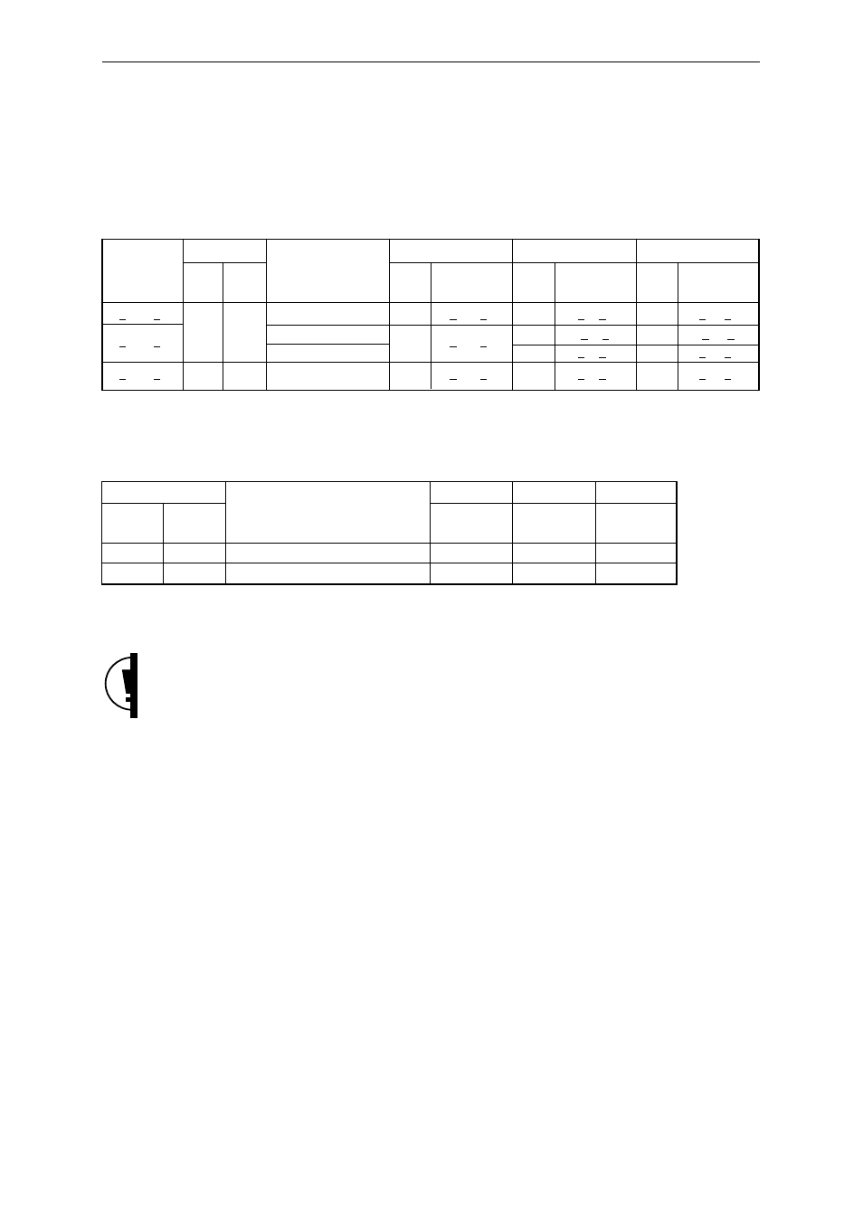
The relationship between the input frequency (fosci) and the SYSCLK, MCLK, and IOCLK multiples and frequencies
is shown in Table 6-4-2, and the relationship between the input frequency (fosci) and the SYSCLK, MCLK, and
IOCLK multiples and frequencies when reset is released is shown in Table 6-4-3.
Table 6-4-2
Relationship between the Oscillation Mode and the SYSCLK, MCLK,
and IOCLK Frequencies
Input frequency
Oscillation mode Clock control register setting
SYSCLK
MCLK
IOCLK
fosci (MHz)
CKSEL
PLL
Register symbol: CKCTR Multiple
Frequency
Multiple
Frequency
Multiple
Frequency
Address: x’32004000
fsys (MHz)
fc (MHz)
fio (MHz)
8
≤
fosci
≤
15
MCK [1:0]= 10
1
8
≤
fsys
≤
15
4
32
≤
fc
≤
60*
1
8
≤
fio
≤
15
8
≤
fosci
≤
18
H
Used
MCK [1:0] = 01
1
8
≤
fsys
≤
18
2
16
≤
fc
≤
36
1/2
4
≤
fio
≤
9
MCK [1:0] = 00
1
8
≤
fc
≤
18
1/4
2
≤
fio
≤
4.5
8
≤
fosci
≤
20
L
Not used
Not used
1/2
4
≤
fsys
≤
10
1/2
4
≤
fc
≤
10
1/8
1
≤
fio
≤
2.5
*: In the case of the MN1030F01K, the maximum frequency for MCLK is 40 MHz.
Table 6-4-3
Relationship between the Input Frequency and the SYSCLK, MCLK,
and IOCLK Frequencies When Reset Is Released
Oscillation mode
Clock control register setting
SYSCLK
MCLK
IOCLK
CKSEL
PLL
Register symbol: CKCTR
Multiple
Multiple
Multiple
Address: x’32004000
H
Used
MCK [1:0] = 00
1
1
1/4
L
Not used
Not used
1/2
1/2
1/8
Note: When changing the input frequency during operation, be certain to enter the reset mode and set the CKSEL
pin to the prescribed value during reset mode.
The input frequency ranges shown here are preliminary. When using this LSI, contact our sales office for
the product specifications.