Panasonic MN103001G/F01K User Manual
Page 319
Serial Interface
13-17
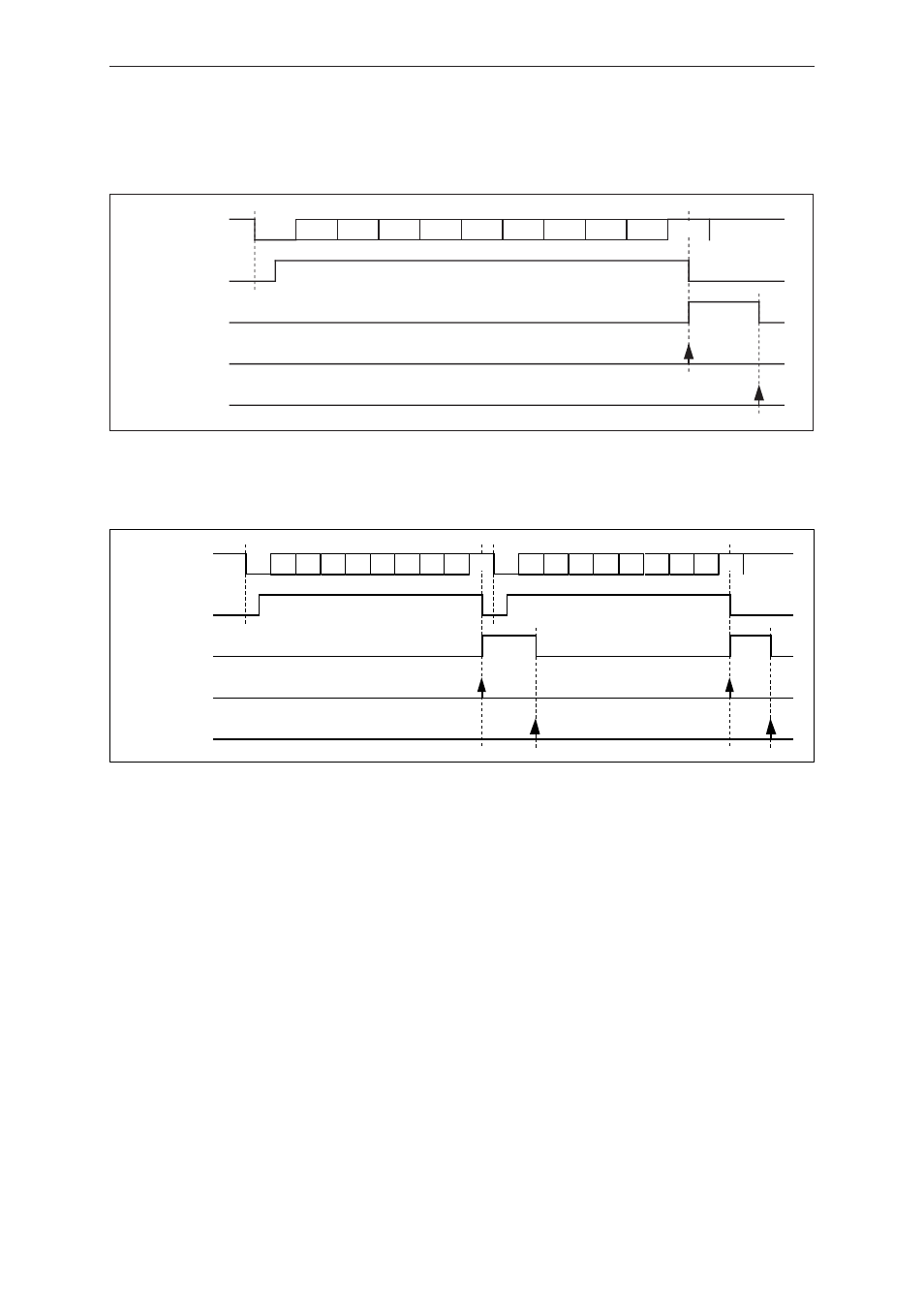
• Transfer with 8-bit data length, parity on, and 1 stop bit
Fig. 13-2-11 Timing Chart (8)
• Two-byte transfer with 7-bit data length, parity on, and 1 stop bit
Fig. 13-2-12 Timing Chart (9)
After reception end (when the SC0RBF flag is "1"), the received data is fetched by reading the SC0RXB.
In the case of a 7-bit transfer, the MSB (bit 7) is "0".
The SC0RXF flag is set to "1" at the start of reception (when the start bit is detected), and is set to "0" at the end of
reception.
The SC0RBF flag is set to "1" at the end of reception, and is set to "0" when SC0RXB is read.
SC0RXF flag
SBI pin
SC0RBF flag
bp1
bp2
bp3
bp4
bp5
bp6
bp7
PTY
bp0
ST
SP
Interrupt request
Data read
SBI pin
bp1 bp2 bp3 bp4 bp5 bp6
bp0
ST
bp1 bp2 bp3 bp4 bp5 bp6
bp0
ST
SC0RXF flag
SC0RBF flag
SP
SP
Interrupt request
Data read
PTY
PTY