2 block diagram – Panasonic MN103001G/F01K User Manual
Page 37
2-3
CPU
2.2
Block Diagram
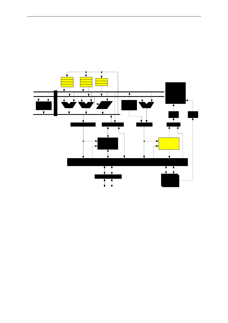
The block diagram for this microcontroller, focusing on the CPU, is shown below.
Fig. 2-2-1 CPU Core Block Diagram
Instruction
queue
Interrupt
control
block
Operand address
AU
LU
Barrel
shifter
AU
Program
counter
block
Instruction address
Instruction
execution
control block
Instruction
decoder
Operand data
Instruction
User
extension
function unit
Internal
peripheral
function
Bus contol block
External interface
Extension interface
Address register
Data register
D0
D1
D2
D3
SP
MDR
PSW
A0
A1
A2
A3
Internal
instruction ROM/
Internal flash
memory
Internal
data RAM