7 control output connection, 4 - 7 control output connection, Warning – Honeywell DCP552 Mark II User Manual
Page 37
4 - 7
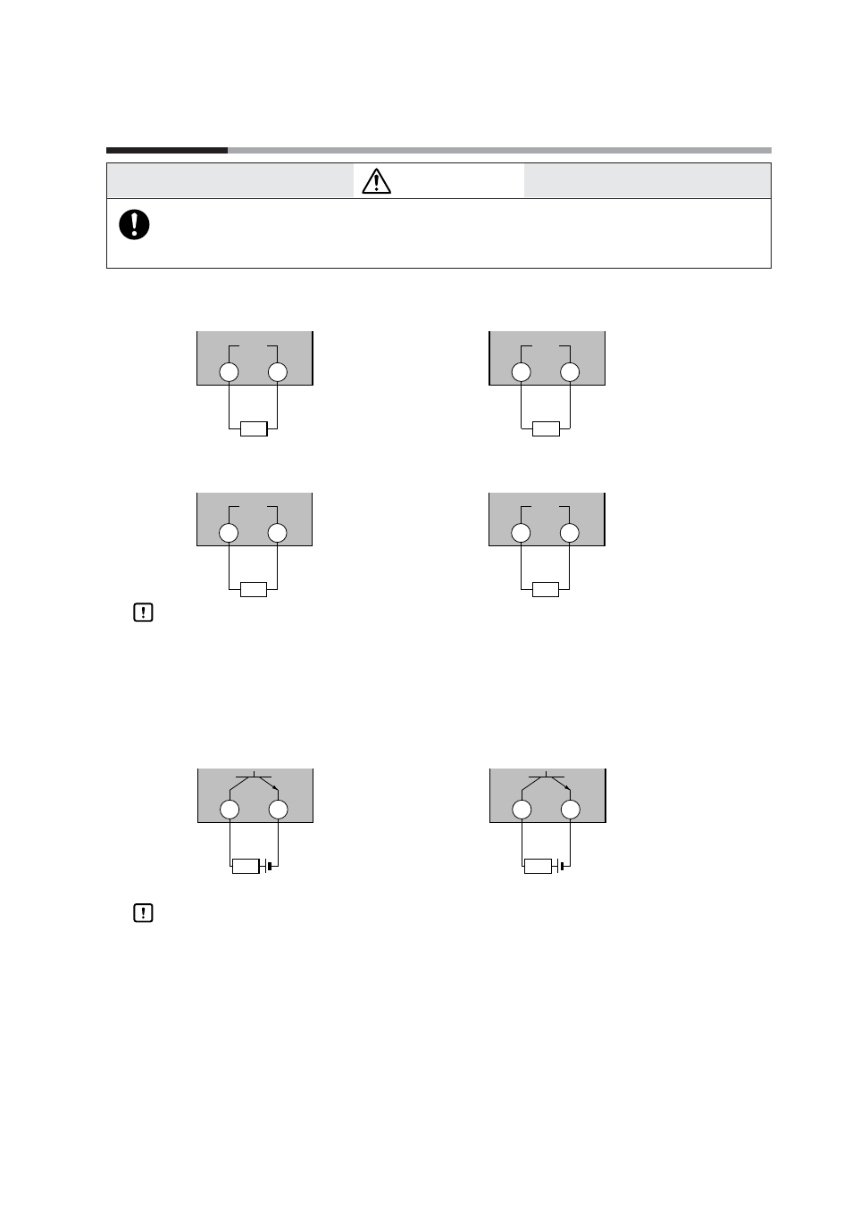
Control Output Connection
●
Current output (5G, 5S)
●
Voltage output (6D)
Handling Precautions
The voltage output is a constant current circuit inside. The SSR used is set
to an optimum voltage to meet the requirements of the load. Enter the
value in the setup data. A normal SSR voltage has been set at the factory
before shipment.
●
Open collector output (8D)
Handling Precautions
• Do not short-circuit the positive (+) terminal of the external power supply
to terminal (43) on the
DCP552
. Doing so causes the open collector
outputs to malfunction. (There is no short-circuit preventing circuit
inside.)
• When connecting a semiconductor load such as a programmable
controller (sequencer), select a module in which the current directions
match.
Use one made inoperative by the leakage current produced when the
digital outputs are shut off.
4-9
43
+ -
Load
44
4 to 20mA DC
Load resistance
less than 6009
4 to 20mA DC
Load resistance
less than 6009
45
+ -
Load
46
+
-
+
-
CH2
CH1
Chapter 4. WIRING
WARNING
Be sure to turn off the power supply when you are installing or removing the
controller.
Failure to do so may cause electric shock or fire.
43
+
44
2 to 22mA DC
With current value
adjustment function
(Setup data
C91
)
SSR
+
-
-
45
+
46
2 to 22mA DC
With current value
adjustment function
(Setup data
C92
)
SSR
+ -
-
CH1
CH2
43
12 to 24V DC
+ -
44
Max. load current : 100mA
Leakage current
when off : less than 0.1mA
Load
45
12 to 24V DC
+ -
46
Max. load current : 100mA
Leakage current
when off : less than 0.1mA
Load
CH2
CH1