Honeywell DCP552 Mark II User Manual
Page 200
12-10
●
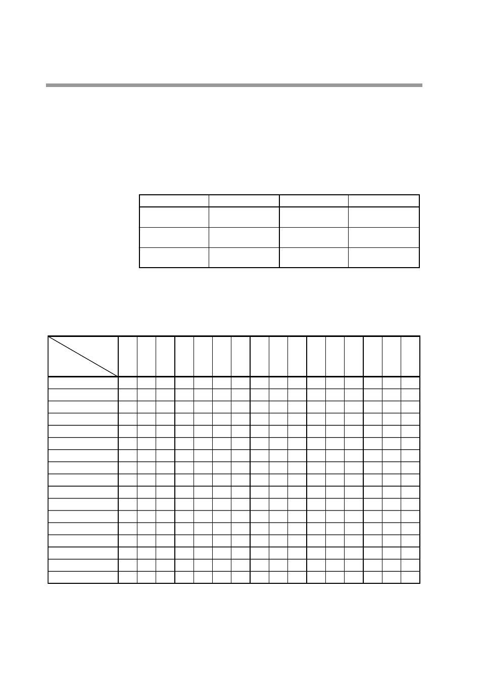
Digital output test for control output (00-04)
Press
SETUP key
until the PROG/SEG display shows (
00-04
).
When the digit of upper display is changed by
↑
,
↓
,
←
,
→
, keys
, the state of 6D
or 8D control output is changed as shown in Table 12-6.
Since the 6D hardware is of current output (8D hardware is of open collector)
specification, the ON/OFF check must be performed in meeting with the
specification.
Table 12-6.
●
Digital output test for event (00-05)
Press
SETUP key
until the PROG/SEG display shows (
00-05
).
Table 12-7. DO
0.0.0.0.
0.0.0.1.
0.0.0.2.
0.0.0.4.
0.0.0.8.
0.0.1.0.
0.0.2.0.
0.0.4.0.
0.0.8.0.
0.1.0.0.
0.2.0.0.
0.4.0.0.
0.8.0.0.
1.0.0.0.
2.0.0.0.
4.0.0.0.
8.0.0.0.
Ñ
ON
С
С
С
С
С
С
С
С
С
С
С
С
С
С
С
DO
Terminal
Number
Upper
Display
Notes: 1. ÒÑÓ in the table means ÒOFFÓ.
2. Since the DO hardware is of open collector specification, the ON/OFF check must be performed in
meeting with the specification.
С
С
ON
С
С
С
С
С
С
С
С
С
С
С
С
С
С
С
С
С
ON
С
С
С
С
С
С
С
С
С
С
С
С
С
С
С
С
С
ON
С
С
С
С
С
С
С
С
С
С
С
С
С
С
С
С
С
ON
С
С
С
С
С
С
С
С
С
С
С
С
С
С
С
С
С
ON
С
С
С
С
С
С
С
С
С
С
С
С
С
С
С
С
С
ON
С
С
С
С
С
С
С
С
С
С
С
С
С
С
С
С
С
ON
С
С
С
С
С
С
С
С
С
С
С
С
С
С
С
С
С
ON
С
С
С
С
С
С
С
С
С
С
С
С
С
С
С
С
С
ON
С
С
С
С
С
С
С
С
С
С
С
С
С
С
С
С
С
ON
С
С
С
С
С
С
С
С
С
С
С
С
С
С
С
С
С
ON
С
С
С
С
С
С
С
С
С
С
С
С
С
С
С
С
С
ON
С
С
С
С
С
С
С
С
С
С
С
С
С
С
С
С
С
ON
С
С
С
С
С
С
С
С
С
С
С
С
С
С
С
С
С
ON
С
С
С
С
С
С
С
С
С
С
С
С
С
С
С
С
С
ON
(5)
↕
(9)
(6)
↕
(9)
(7)
↕
(9)
(8)
↕
(9)
(17)
↕
(9)
(18)
↕
(9)
(19)
↕
(9)
(20)
↕
(9)
(10)
↕
(24)
(11)
↕
(24)
(22)
↕
(24)
(23)
↕
(24)
(27)
↕
(24)
(28)
↕
(24)
(31)
↕
(24)
(32)
↕
(24)
0.0.0.0.
0.0.0.1.
0.0.0.2.
Upper Display
State
All OFF
С
С
Upper Display
State
0.0.0.4.
0.0.0.8.
6D output
CH1 ON
6D output
CH2 ON
8D output
CH1 ON
8D output
CH2 ON
Chapter 12. CALIBRATION