Honeywell DCP552 Mark II User Manual
Page 127
7-28
0: Displayed
1: Not displayed
0
C 57
57
Programming item
event
0: Displayed
1: Not displayed
0
C 58
58
Programming item
PID group, output limiter group
0: Displayed
1: Not displayed
0
C 59
59
Programming item
G.SOAK, PV shift, repeat
0: Displayed
1: Not displayed
0
C 60
60
Programming item
PV start, cycle, pattern link
0: RAMP-X and RAMP-T (q) combined
1: RAMP-X and RAMP-E (ÆSP) combined
0
C 61
61
Programming system
0: hours, min (SPU/hour for RAMP-T)
1: min, sec (SPU/min for RAMP-T)
2: 0.1 sec (SPU/sec for RAMP-T)
0
C 62
62
Programming time unit
0: remaining segment time
1: total operation time (after READY ® RUN start)
0
C 63
63
Time display
(display panel 1 and 2)
0 to 16
0 indicates no CH2 event
[Description:]
When a change in set values cause multiple output
points for a code event to overlap the CH1 and CH2
division, the event configuration setting output points is
changed so that only CH1 is used.
0
C 64
64
Event no. division (first CH2
number)
0 to 4
A setting of 0 means no decimal point and a setting
between 1 and 4 indicates the number of decimal digits.
[Description:]
This setting is reflected in PVU (SPU (CH1)) units.
1
C 65
65
SP decimal point position
(CH1)
PV1 range
lower limit
C 66
66
SP limit lower limit (CH1)
-19999 to +20000 SPU (CH1)
[Description:]
When
C01
to
C06
are set,
C66
and
C67
are
automatically set as the upper limit and lower limit of the
range.
PV1 range
upper limit
C 67
67
SP limit upper limit (CH1)
PV2 range
lower limit
C 69
69
SP limit lower limit (CH2)
-19999 to +20000 SPU (CH2) on a model without CP
compensation.
0 to 2000 SPU(CH2) on a model with CP compensation.
[Description:]
When
C11
to
C16
are set,
C69
and
C70
are
automatically set as the upper limit and lower limit of the
PV1 range.
The factory default setting for models with CP
compensation is
C69
=0.000,
C70
=2.000.
0
C 71
71
External switch input RSW5
0 : NOP (does not function)
1 : RAMP-E
2 : FAST
3 : G.SOAK is cleared using OR
4 : G.SOAK is cleared using AND
5 : MANUAL/AUTO
6 : AT start/terminate
7 : NOP (does not function)
8 : Auto load
9 : NOP (does not function)
10: NOP (does not function)
11: O
2
sensor check
PV2 range
upper limit
C 70
70
SP limit upper limit (CH2)
0 to 4 on a model without CP compensation.
0 to 3 on a model with CP compensation.
A setting of 0 means no decimal point and a setting
between 1 and 4 indicates the number of decimal digits.
[Description:]
This setting is reflected in PVU (SPU (CH2)) units.
The factory default setting for models without CP
compensation is 1.
The factory default setting for models without CP
compensation is 3.
1 or 3
C 68
68
SP decimal point position
(CH2)
0
C 72
72
External switch input RSW6
0
C 73
73
External switch input RSW7
0
C 74
74
External switch input RSW8
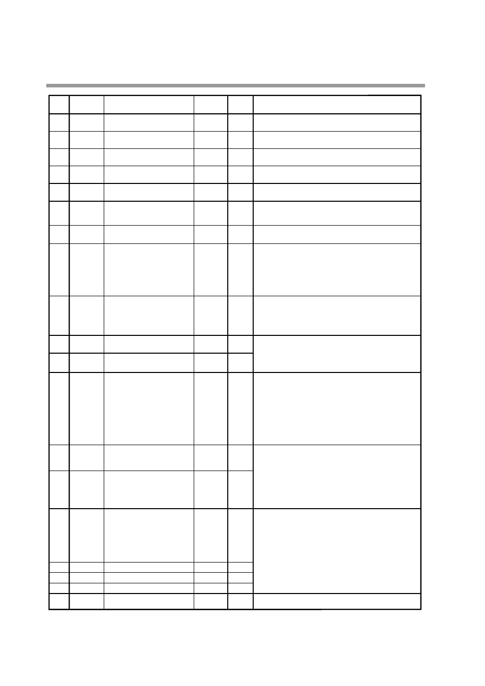
Item code
Item
No.
User
settings
Settings and descriptions
Factory default
settings
0: BCD4 bits + BCD2 bits
1: binary 7 bits
0
C 75
75
External switch input RSW9
to 14 (program selection)
Chapter 7. PARAMETER SETUP