Honeywell DCP552 Mark II User Manual
Page 202
12-12
●
PV zero, span
(1) PV zero adjustment
(a) Press
SETUP key
until the PROG/SEG display shows (
01-03
).
(b) Adjust your calibration device to an output signal equal to the 0% range
value (See Table 12-9), the signal need to be on the input for 10 to 15
seconds.
(c) Press
ENTER key
after display stabilizes.
(2) PV span adjustment
(a) Press
SETUP key
until the PROG/SEG display shows (
01-04
).
(b) Adjust your calibration device to an output signal equal to the 100% range
value (See Table 12-9).
(c) Press
ENTER key
after display stabilizes.
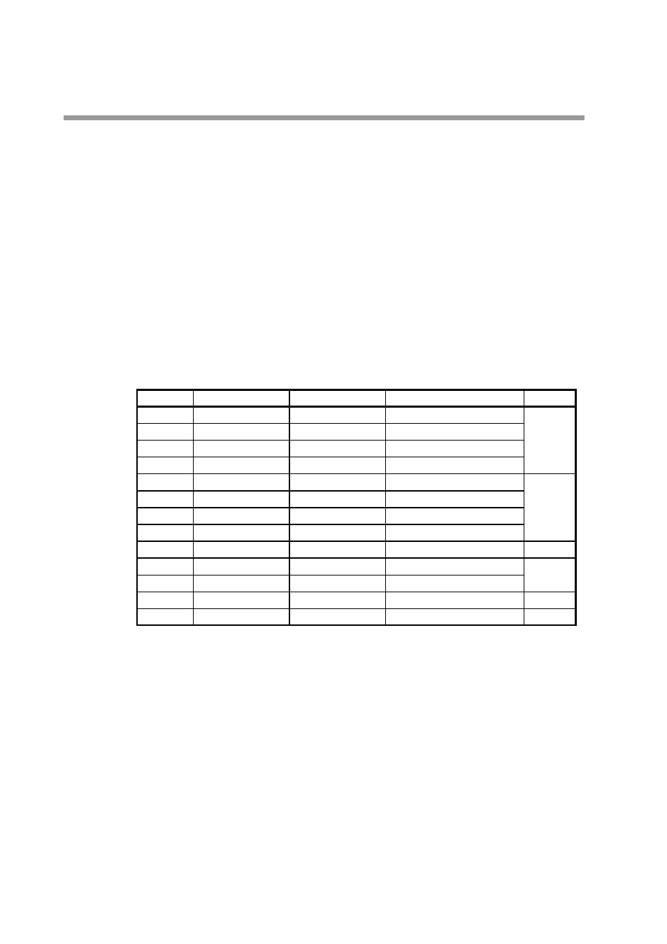
Table 12-9.
●
Writing into EEPROM
Press
SETUP key
until the PROG/SEG display shows (
01-05
).
Scroll
↑
,
↓
,
←
,
→
, keys
to show (
1.1.1.1.
) on the upper display.
Press
ENTER key
.
Gain No.
0
1
2
3
4
5
6
7
8
9
10
11
12*
PV Input 0%
PV Input 100%
Ð5.000mV
Ð10.000mV
0.000mV
0.000mV
0.000mV
Ð1.000V
0.000V
0.000V
4.000mA
209
209
19
0.000V
10.000mV
18.000mV
36.000mV
52.000mV
100.000mV
1.000V
5.000V
10.000V
20.000mA
1409
4809
1009
1.250V
ConnectingPosition
Between A(+) and B(Ð)
Between A(+) and B(Ð)
Between A(+) and B(Ð)
Between A(+) and B(Ð)
Between A(+) and B(Ð)
Between A(+) and B(Ð)
Between A(+) and B(Ð)
Between A(+) and B(Ð)
Between C(+) and B(Ð)
Between A(+) and B(Ð)
Between A(+) and B(Ð)
Between C(+) and B(Ð)
Between C(+) and B(Ð)
Note:
*
; If model isnÕt Carbon Potential, it isnÕt necessary to calibrate this item.
Figure
Fig.12-5
Fig.12-8
Fig.12-9
Fig.12-6
Fig.12-7
Fig.12-10
Chapter 12. CALIBRATION