Pid parameter (ch1) setting – Honeywell DCP552 Mark II User Manual
Page 117
7-18
■
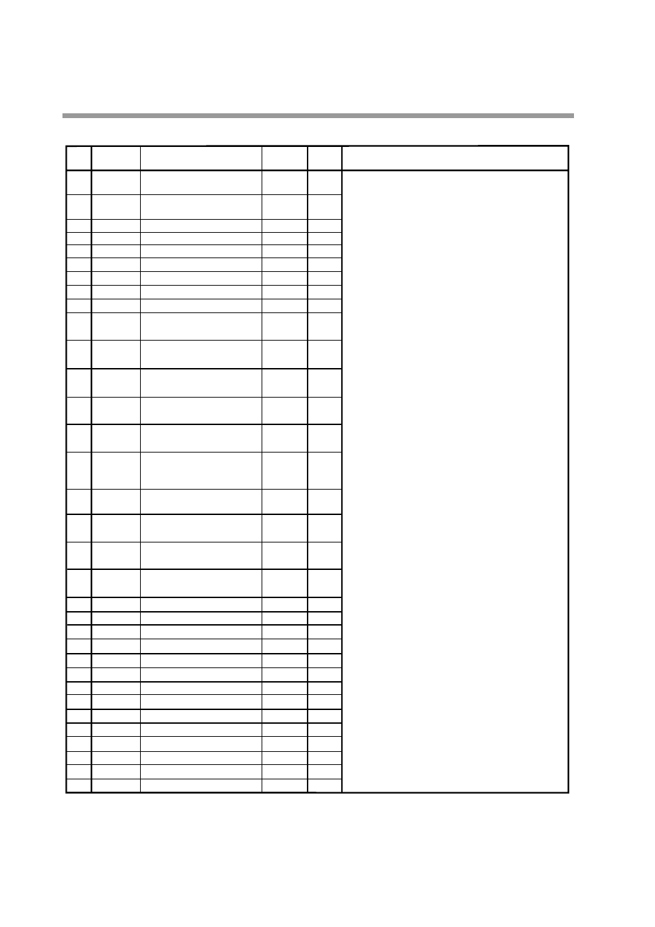
PID parameter (CH1) setting
P
l
d
rE
oL
oH
CP
tP
[Description:]
¥ When
P
is set to 0.0, ON-OFF control is on and
l
,
d
and
rE
settings display Т-----У and setting cannot be performed.
¥ When the I setting is not equal to 0, Т-----У is displayed for
rE
and setting cannot be performed.
¥ Although a low
P
setting improves control, overshoot and
hunting is more likely to occur.
¥ Although a low
l
setting improves tracking, cycling caused by
integral operation occurs more often.
¥ Although a low
d
setting makes it easier to suppress
overshoot, hunting is more likely to occur due to reactions to
minute PV action.
In normal temperature control, derivative time should be
between 1/3 to 1/4 of the integral time.
Since derivative operation is a cause of hunting in pressure
and flow control, set
d
to 0.0 to turn off derivative action or
set a low value.
¥ The
rE
setting is used to eliminate offset caused by
proportional action (no integral action) and sets a suitable
deviation of 0.
¥ The
oL
and
oH
settings also operate as integral limiters.
When
oL
or
oH
manipulated variable reaches the upper or
lower limit, they turn off integral action and prevents reset
windup that occurs when PV has not risen for a long time.
¥ The
CP
setting is the point where switching occurs between
PID groups A1 to A7.
¥
tP
is the tuning point where
P
,
I
and
D
settings in groups A1
to A7 are automatically tuned starting from A1.
[Note:]
CH1 PID parameter settings are described on this page. CH1
PID parameters are set when the PID key is pressed when
CH1 is selected (when the EG1 LED is on) during program
operation in the normal display mode.
100.0
P-1
1
Proportional band (PID group 1)
0
I-1
2
Integral time (PID group 1)
0
d-1
3
Derivative time (PID group 1)
50.0
rE -1
4
Manual reset (PID group 1)
0.0
oL-1
5
Manipulated variable lower limit (Output limiter group 1)
100.0
oH-1
6
Manipulated variable upper limit (Output limiter group 1)
100.0
P-2
7
Proportional band (PID group 2)
0
I-2
8
Integral time (PID group 2)
0
d-2
9
Derivative time (PID group 2)
50.0
rE-2
10
Manual reset (PID group 2)
0.0
oL-2
11
Manipulated variable lower limit
(Output limiter group 2)
100.0
oH-2
12
Manipulated variable upper limit
(Output limiter group 2)
100.0
P-3
13
Proportional band (PID group 3)
0
I-3
14
Integral time (PID group 3)
0
50.0
d-3
15
Derivative time (PID group 3)
rE-3
16
Manual reset (PID group 3)
0.0
oL-3
17
Manipulated variable lower limit
(Output limiter group 3)
100.0
oH-3
18
Manipulated variable upper limit
(Output limiter group 3)
100.0
P-4
19
Proportional band (PID group 4)
0
I-4
20
Integral time (PID group 4)
0
d-4
21
Derivative time (PID group 4)
50.0
rE-4
22
Manual reset (PID group 4)
0.0
oL-4
23
Manipulated variable lower limit (Output limiter group 4)
100.0
oH-4
24
Manipulated variable upper limit (Output limiter group 4)
100.0
P-5
25
Proportional band (PID group 5)
0
I-5
26
Integral time (PID group 5)
0
d-5
27
Derivative time (PID group 5)
50.0
rE-5
28
Manual reset (PID group 5)
0.0
oL-5
29
Manipulated variable lower limit (Output limiter group 5)
100.0
oH-5
30
Manipulated variable upper limit (Output limiter group 5)
100.0
P-6
31
Proportional band (PID group 6)
0
I-6
32
Integral time (PID group 6)
0
d-6
33
Derivative time (PID group 6)
: 0.0 to 1000.0%
ON-OFF control when set to 0.0
: 0 to 3600sec
No integral operation when set to 0
: 0 to 1200sec
No derivative operation when set to 0
: 0.0 to 100.0%
: Ð5.0 to manipulated variable upper limit %
: Manipulated variable lower limit to +105.0%
: Ð19999 to +20000 SPU
: Ð19999 to +20000 SPU
Item code
Item
No.
User
settings
Settings and descriptions
Factory default
settings
Chapter 7. PARAMETER SETUP