Wiring diagram for multiple connections, Network termination, Recommended cable – Yaskawa Z1000U HVAC Matrix Bypass User Manual
Page 418: Rs-485 interface, E.2 connecting to a network
u
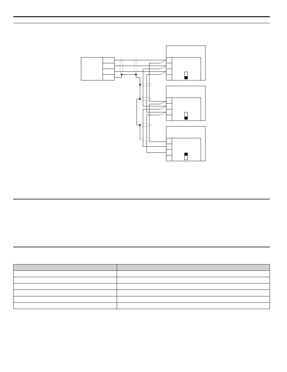
Wiring Diagram for Multiple Connections
n
RS-485 Interface
CONTROLLER
(customer-supplied)
1
2
3
4
+
-
SHLD
Bypass Drive
S1
OFF
TB3
SHLD
TXRX-
TXRX+
IG5
1
2
3
4
Bypass Drive
S1
OFF
TB3
SHLD
TXRX-
TXRX+
IG5
ON
1
2
3
4
Bypass Drive
S1
SHLD
TXRX-
TXRX+
IG5
Bypass
Control
Board A2
Bypass
Control
Board A2
Bypass
Control
Board A2
TB3
COMMON
Figure E.2 Connection Diagram for Multiple Connections
Note:
Turn on DIP switch S1 on the bypass controller located at the end of the network. If DIP switch S1 is missing place an external 120 ohm
resistor across terminals TXRX+ and TXRX–. All other slave devices must have this DIP switch set to the OFF position (or if S1 is missing,
no external resistor is used).
u
Network Termination
The two ends of the P1 network line have to be terminated with a 120 ohm resistor between the TXRX+ and TXRX- signals.
The bypass has a built in termination resistor that can be enabled or disabled using DIP switch S1. If a bypass is located at the
end of a network line, enable the termination resistor by setting DIP switch S1 to the ON position. Disable the termination
resistor on all slaves that are not located on the network line end.
Note:
Some bypass controllers do not have DIP switch S1. If this is the case, place an external 120 ohm resistor across the TXRX+ and TXRX-
signals if the bypass controller is at the end of a network line.
u
Recommended Cable
Table E.2 APOGEE FLN Cable Specifications
Specification
Description
Cable Configuration
Twisted Shielded Pair
Gauge
18-20 AWG (Solid or Stranded)
Wire Lay
6 twists per foot
Shields
100% foil with drain wire
NEC Type
UL Type CMP
Temperature
60 °C or higher
E.2 Connecting to a Network
418
YASKAWA SIEP YAIZ1D 01A Z1000U HVAC MATRIX Drive Bypass Technical Manual