B: application, B1: operation mode selection, B2: dc injection braking – Yaskawa Z1000U HVAC Matrix Bypass User Manual
Page 311: B.3 b: application

B.3 b: Application
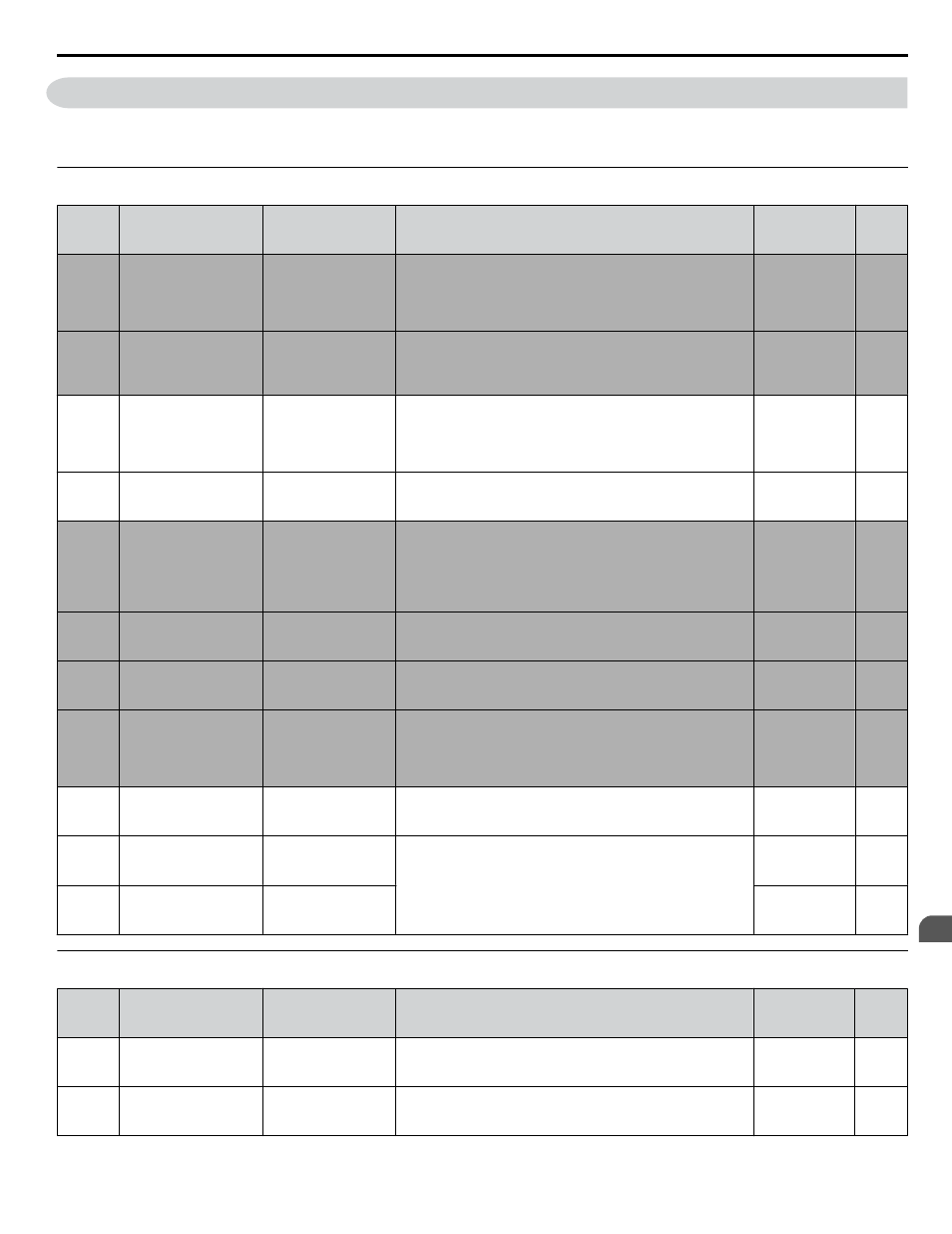
Application parameters configure the source of the Run command, DC Injection Braking, Speed Search, timer functions, PID
control, Energy Savings, and a variety of other application-related settings.
u
b1: Operation Mode Selection
No.
(Addr.
Hex)
Name
LCD Display
Description
Values
Page
b1-01
(0180)
Frequency Reference
Selection for AUTO
mode
Ref Source 1
0: Operator
1: Analog Input
2: Serial Com
3: Option PCB
0: HOA keypad
1: Terminals (Analog Input Terminals)
2: Serial communications (APOGEE FLN, BACnet,
MEMOBUS/Modbus, or Metasys N2)
3: Option card
Default: 1
Range: 0 to 3
–
b1-02
(0181)
Run Command
Selection for AUTO
mode
Run Source 1
1: Digital Inputs
2: Communication
3: Option PCB
1: Control Circuit Terminal
2: Serial communications (APOGEE FLN, BACnet,
MEMOBUS/Modbus, or Metasys N2)
3: Option card
Default: 2
Range: 1 to 3
–
b1-03
(0182)
Stopping Method
Selection
Stopping Method
0: Ramp to Stop
1: Coast to Stop
2: DCInj to Stop
3: Coast w/Timer
0: Ramp to stop
1: Coast to stop
2: DC Injection Braking to stop
3: Coast with timer
Default: 1
Range: 0 to 3
b1-04
(0183)
Reverse Operation
Selection
Reverse Oper
0: Reverse Enabled
1: Reverse Disabled
0: Reverse enabled
1: Reverse disabled
Default: 1
Range: 0, 1
b1-08
(0187)
Run Command
Selection in
Programming Mode
RUN dur PRG Mode
0: Run
Disabled@PRG
1: ModeRun
Enabled@PRG
2: Prg only @ Stop
0: Run command is not accepted while in Programming Mode
1: Run command is accepted while in Programming
2: Prohibit entering Programming Mode during Run
Default: 0
Range: 0 to 2
–
b1-11
(01DF)
Drive Delay Time
Setting
Run Delay Time
After a Run command is entered, the drive output waits until
this delay time has passed before starting.
Default: 0 s
Min.: 0
Max.: 600
–
b1-14
(01C3) Phase Order Selection
Rotation Sel
0: Standard
1: SwitchPhaseOrder
0: Standard
1: Switch phase order (reverses the direction of the motor)
Default: 0
Range: 0, 1
–
b1-17
(01C6)
Run Command at Power
Up
Run Cmd @ Pwr On
0: Cycle Ext Run
1: Accept Ext Run
0: Disregarded.
A new Run command must be issued after power up.
1: Allowed.
Motor will start immediately after power up if a Run command
is already enabled.
Default: 1
Range: 0, 1
–
b1-24
(0B2C)
Commercial Power
Operation Switching
Selection
CommerclPwrSwSel
0: Disabled
1: Enabled
0: Disabled
1: Enabled
Default: 0
Range: 0, 1
b1-25
(0B2D)
Commercial Power
Supply Operation
Cancellation Level
Freq Deviate Lvl
Sets the judgement value of the hysteresis comparator in the
judgment section for the commercial power switching function
in increments of 0.1 Hz.
Default: 1.0 kHz
Min.: 0.4
Max.: 6.0
b1-26
(0B2E)
Commercial Power
Supply Operation
Switching Level
Freq Accept Lvl
Default: 0.2 kHz
Min.: 0.0
Max.: 3.0
u
b2: DC Injection Braking
No.
(Addr.
Hex)
Name
LCD Display
Description
Values
Page
b2-01
(0189)
DC Injection Braking
Start Frequency
DCInj Start Freq
Sets the frequency at which DC Injection Braking starts when
“Ramp to stop” (b1-03 = 0) is selected.
Default: 0.5 Hz
Min.: 0.0
Max.: 10.0
b2-02
(018A)
DC Injection Braking
Current
DCInj Current
Sets the DC Injection Braking current as a percentage of the
drive rated current.
Default: 50%
Min.: 0
Max.: 100
B.3 b: Application
YASKAWA SIEP YAIZ1D 01A Z1000U HVAC MATRIX Drive Bypass Technical Manual
311
B
Parameter List
