Yaskawa Z1000U HVAC Matrix Bypass User Manual
Page 175
No.
Name
Setting Range
Default
H3-01
Terminal A1 Signal Level Selection
0 to 3
0
Setting 0: 0 to 10 V with Zero Limit
The input level is 0 to 10 Vdc with zero limit. The minimum input level is limited to 0%, so that a negative input signal due
to gain and bias settings will be read as 0%.
Setting 1: 0 to 10 V without Zero Limit
The input level is 0 to 10 Vdc without zero limit. If the resulting voltage is negative after being adjusted by gain and bias
settings, then the motor will rotate in reverse.
Setting 2: 4 to 20 mA Current Input
The input level is 4 to 20 mA. Negative input values by negative bias or gain settings are limited to 0%.
Setting 3: 0 to 20 mA Current Input
The input level is 0 to 20 mA. Negative input values by negative bias or gain settings are limited to 0%.
n
H3-02: Terminal A1 Function Selection
Selects the input signal level for analog input A1.
Refer to Multi-Function Analog Input Terminal Settings on page 178
instructions on adjusting the signal level.
No.
Name
Setting Range
Default
H3-02
Terminal A1 Function Selection
0 to 26
0
n
H3-03, H3-04: Terminal A1 Gain and Bias Settings
Parameter H3-03 sets the level of the selected input value that is equal to 10 Vdc (20 mA) input at terminal A1 (gain).
Parameter H3-04 sets the level of the selected input value that is equal to 0 V (4 mA, 0 mA) input at terminal A1 (bias).
Use both parameters to adjust the characteristics of the analog input signal to terminal A1.
No.
Name
Setting Range
Default
H3-03
Terminal A1 Gain Setting
-999.9 to 999.9%
100.0%
H3-04
Terminal A1 Bias Setting
-999.9 to 999.9%
0.0%
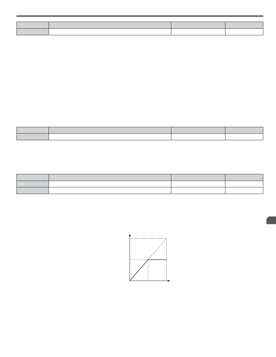
Setting Examples
• Gain H3-03 = 200%, bias H3-04 = 0, terminal A1 as frequency reference input (H3-02 = 0):
A 10 Vdc input is equivalent to a 200% frequency reference and 5 Vdc is equivalent to a 100% frequency reference. Since
the drive output is limited by the maximum frequency parameter (E1-04), the frequency reference will be equal to E1-04
above 5 Vdc.
H3-01 = 0
10 V
5 V
0 V
Gain = 200 %
100 %
Frequency
reference
Bias = 0 %
E1-04
Figure 5.32 Frequency Reference Setting by Analog Input with Increased Gain
• Gain H3-03 = 100%, bias H3-04 = -25%, terminal A1 as frequency reference input:
An input of 0 Vdc will be equivalent to a -25% frequency reference.
When parameter H3-01 = 0, the frequency reference is 0% between 0 and 2 Vdc input.
5.7 H: Terminal Functions
YASKAWA SIEP YAIZ1D 01A Z1000U HVAC MATRIX Drive Bypass Technical Manual
175
5
Programming