Tool depiction, Material-removal graphic, 3 v iews – HEIDENHAIN SW 548328-05 User Manual
Page 466
466
Graphic simulation
6.3 V
iews
Tool depiction
You adjust by soft key whether the tool cutting edge or the light dot is
shown (see table at right).
The tool cutting edge is shown with the correct angles and cutting
radius, as defined in the tool database.
Light-dot view: A white square (light dot) is shown at the currently
programmed position. The light dot represents the position of the
imaginary cutting edge.
Depicting the tool holder during machining simulation
The control can depict the associated tool holder with the
corresponding dimensions in addition to the tool's cutting edge. The
requirements for this are:
Creating a new tool holder in the holder editor or selecting an
existing holder
Describing the tool holder with the required parameters (type,
dimensions and position)
The appropriate tool holder must be assigned to the tool (HID)
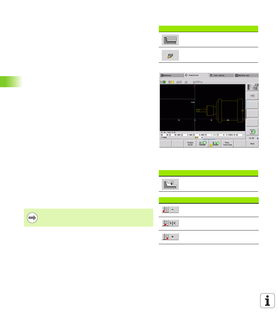
Material-removal graphic
The material-removal graphics shows the workpiece blank as a "filled
surface." When the tool tip passes through the workpiece blank, the
workpiece area covered by the tool is erased in the graphic.
The material-removal graphic mode shows all paths of traverse
according to the programmed speed. The 2-D material-removal
graphic mode is only available in side view (XZ). You activate this type
of simulation by soft key (see table at right).
Soft keys for miscellaneous functions
Switches between wire-frame
graphics and cutting-path graphics.
Switches between light-dot and
cutting-edge view.
Soft keys for miscellaneous functions
Activates the 2-D material-removal
graphic
Menu for the material-removal graphic
Slows the material-removal
graphic.
Material removal graphic at the
programmed feed rate
Accelerates the material-removal
graphic.
You can change the speed of simulation in the metal-
removal graphic by using the keys in the table at right.