Contour form elements – HEIDENHAIN SW 548328-05 User Manual
Page 382
382
ICP programming
5.8 Cont
our elements of a t
u
rn
ing cont
our
Contour form elements
Chamfer/rounding arc
Select the form elements.
Select a chamfer.
Select rounding arc.
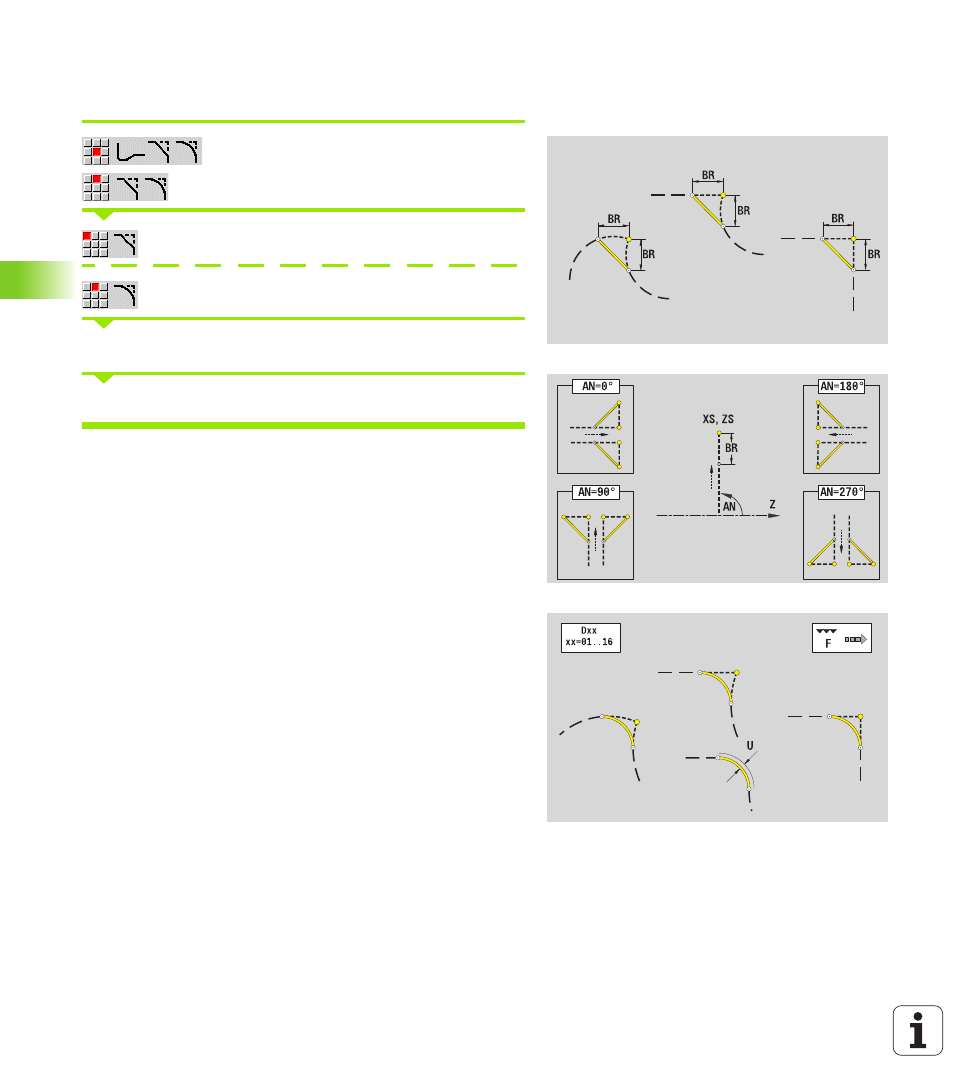
Enter the chamfer width BR
or the rounding radius BR.
Chamfer/rounding arc as first element: Enter element position AN.
Chamfers/rounding arcs are defined on contour corners. A "contour
corner" is the point of intersection between the approaching and
departing contour elements. A chamfer or rounding cannot be
calculated until the departing contour element is known.
ICP integrates the chamfer/rounding arc in smart.Turn on the basic
element G1, G2 or G3.
Contour begins with a chamfer or a rounding arc: Enter the
position of the intended corner as starting point. Then, in the form
element menu, select chamfer or rounding arc. Since the introducing
contour element is missing, you enter the element position AN to
clearly define the position of the chamfer or rounding arc.
Example of an outside chamfer at start of contour: If you program
"element position AN=90°," the imaginary approaching reference
element is a transverse element in the positive +X axis direction (see
figure).
ICP converts a chamfer or rounding arc at the start of the contour to a
linear or circular element.
Parameters
BR
Chamfer width/rounding radius
AN
Element position
U, F, D, FP: See machining attributes on page 357