Grass Valley Kameleon Series v.5.1.0 User Manual
Page 16
16
Kameleon Series Instruction Manual
Installation
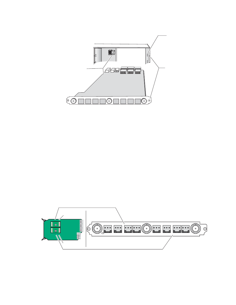
Figure 4. Installing Passive Rear Module
3.
Verify that the module connector seats properly against the midplane.
4.
Using a crossblade screwdriver, tighten the two screw locks to secure
the module in the frame.
5.
If an ADC and/or DAC audio submodule option has been ordered, the
submodule will be provided with the front processing media module.
Placement of the submodule depends on the desired audio I/O config-
uration from the rear module type being used. The installation of the
submodule will determine the functionality of the input and output
audio connectors on each side of the rear module.
As illustrated in
, Submodule 1 is wired to the connectors on
the left side of the rear module. Submodule 2 is wired to the right side
connectors.
Figure 5. Submodule/Rear Connector Relationship
Refer to the rear module cabling information tables for correct place-
ment of the submodules to match your requirements as follows:
Rear alignment
post and receptacle
Screw lock
(both sides)
8173-05r1
2000 frame (rear view)
KAM passive rear module
Board edge guides
(both sides)
8173_33r2
Submodule 1
Wired to left side connectors
Wired to right side connectors
Submodule 2
KAM-AA Rear connectors shown,
same relationship for other rear modules