Hardware connections, Cable connections – Grass Valley Imagestore 750 v.3.0.1 User Manual
Page 83
67
Imagestore 750
User Manual
•
When a panel acquires a channel, it causes the NV9000 system to make appropriate router
switches from the sources being fed by the channel outputs to the monitor wall destina-
tions.
This is the preferred method despite its requiring configuration of both the Imagestore 750
and iMC panel(s). (See
on page 85 and
•
When a panel acquires a channel, it can fire a “channel acquisition salvo” for the channel/
panel combination to make the appropriate router switches for the monitor wall. The disad-
vantage with using salvos is that every existing panel configuration must be updated when
new channels are added to the broadcast facility.
See
Applicable Publications and Tools
on page 3 for information about software tools.
Hardware Connections
Installing the Imagestore 750 and configuring it to operate with an NV9000 system and iMC
control panels is relatively simple if you complete a few specific (and simple) tasks.
Cable Connections
Installing the Imagestore 750 master control system involves making cable connections and
describing those connections in NV9000-SE Utilities, in the Imagestore 750 Configurator, and in
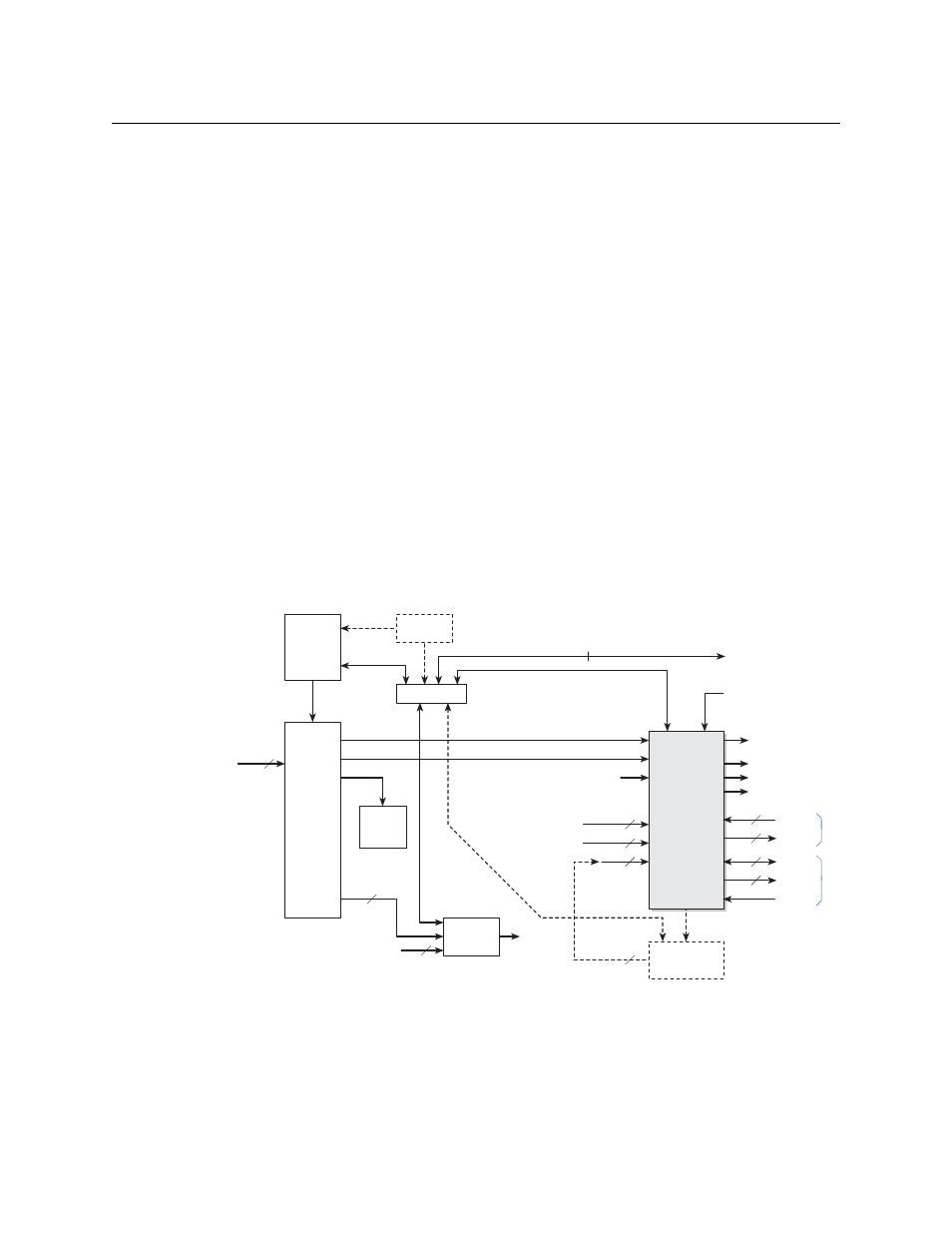
various iMC control panel configurations. These are the basic connections:
Fig. 5-2: Master Control System - Cable Connections
The NV9000 system controls an NVISION series digital video router (such as an NV8576 or
CR3232-HD). The router provides signals that are controlled by the Imagestore 750. The Images-
tore 750 receives commands from automation and master control panels and relays those
Other (SDI)
Monitor
Wall
Kaleido-X
Ethernet Switch
Sources
PGM
PVW
CLN
MON
Auxiliary
Device
Destinations
Video Ref.
A IN
B IN
IS A
IS B
IS AUX
Fill1, Key1
HD or SD
Router
Imagestore
750
2
Fill2, Key2 2
Fill3, Key3 2
NV9000
Automation
(COM1COM4)
AES Out
GPIO
Metadata
LTC
16
4
AES In
16
16
MON m
Master Control
Network
Control Panels
Intuition XG
RS-232
Config PC
(optional)
2