General purpose interface (gpi) – Grass Valley Imagestore 750 v.3.0.1 User Manual
Page 63
47
Imagestore 750
User Manual
The Imagestore 750’s monitor output is used typically for monitoring video at a number of
different points within the Imagestore 750. The monitor output audio mix can also be changed
dynamically using ‘Audio Output Monitor Multiplexor’. (See
General Purpose Interface (GPI)
The ports of the dedicated general-purpose interface (GPI) can be used either to trigger the
execution of a series of internal pre-programmed commands (input) or to monitor the status of
the Imagestore 750 (output). The Imagestore 750’s GPI has 16 input/output ports.
GPI numbering is zero-based for pinouts, automation, and the front panel. Use GPIs
numbered 0–15.
When used as an input, a GPI input is activated as follows:
GPI On
When the GPI pin is connected to 0V.
GPI Off
When a GPI pin is not connected. (The GPI signal pin gets pulled high.)
When used as an output, a GPI output is as follows:
GPI Active(On)
The GPI output pin is internally driven to ground by a Darlington
transistor (Active low is represented by +0.7V or less.)
GPI Inactive(Off)
The GPI output pin is internally pulled high.
Lamps or relays attached to a GPI output port can use the GP_+5V fused supply (pin 7) but the
maximum current drawn should not exceed 500mA.
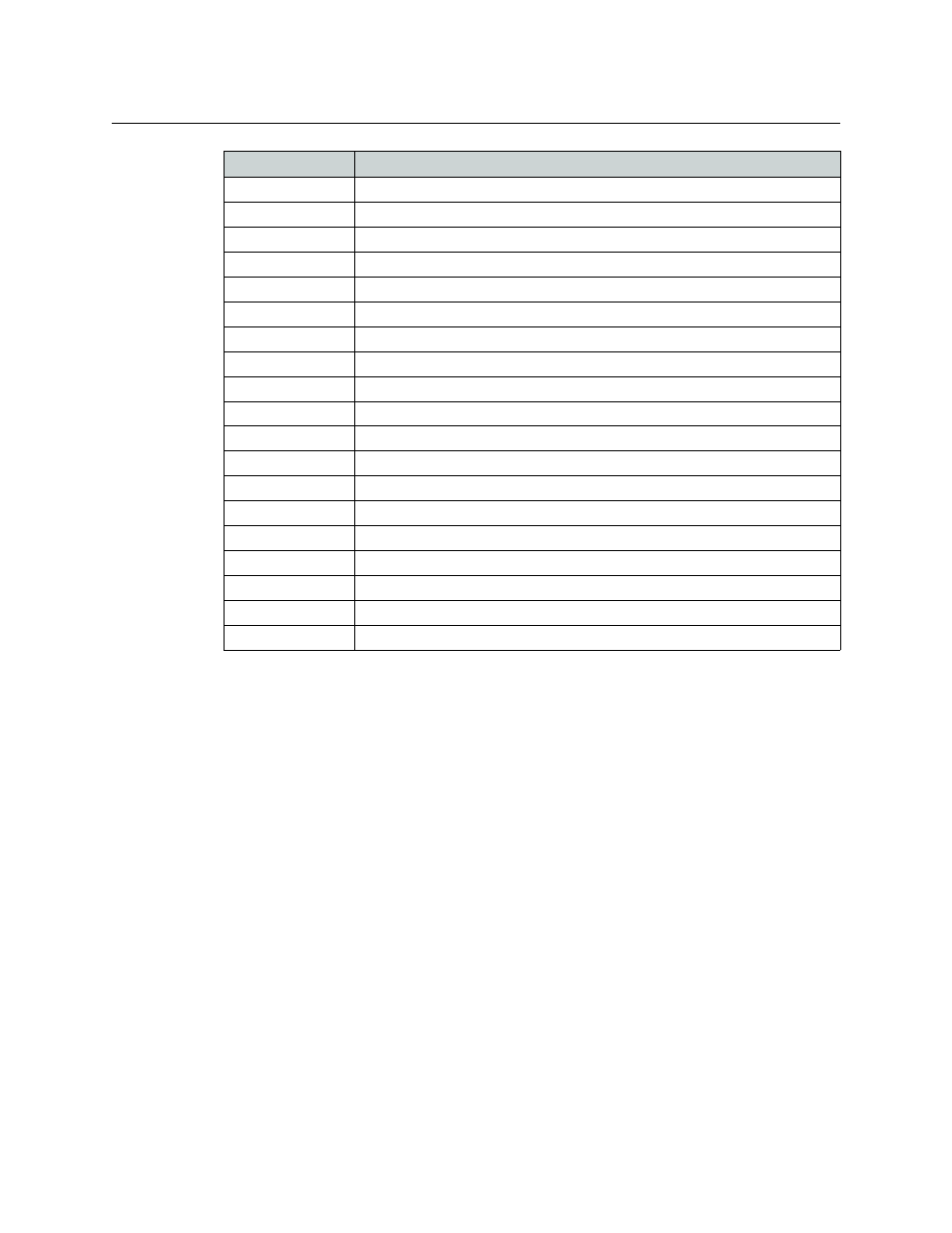
Store 2 Key
Selects outputs from Store 2 Key as the Monitor Output
Store 3 Fill
Selects outputs from Store 3 Fill as the Monitor Output
Store 3 Key
Selects outputs from Store 3 Key as the Monitor Output
Store 4 Fill
Selects outputs from Store 4 Fill as the Monitor Output
Store 4 Key
Selects outputs from Store 4 Key as the Monitor Output
SDI Fill-1
Selects a copy of SDI Fill-1 input as the Monitor Output
SDI Key-1
Selects a copy of SDI Key-1 input as the Monitor Output
SDI Fill-2
Selects a copy of SDI Fill-2 input as the Monitor Output
SDI Key-2
Selects a copy of SDI Key-2 input as the Monitor Output
Colour 1
Selects a copy of Color Field 1 as the Monitor Output
Colour 2
Selects a copy of Color Field 2 as the Monitor Output
Colour 3
Selects a copy of Color Field 3 as the Monitor Output
Colour 4
Selects a copy of the V-fade color as the Monitor Output
Pattern 1
Selects a copy of Test Pattern 1 as the Monitor Output
Pattern 2
Selects a copy of Test Pattern 2 as the Monitor Output
PGM DVE1
Selects a copy of PGM DVE Input 1 as the Monitor Output
PGM DVE2
Selects a copy of PGM DVE Input 2 as the Monitor Output
PVW DVE1
Selects a copy of PVW DVE Input 1 as the Monitor Output
PVW DVE2
Selects a copy of PVW DVE Input 2 as the Monitor Output
Selection
Description
Table 4-14: Monitor output options