Video inputs and outputs – Grass Valley Imagestore 750 v.3.0.1 User Manual
Page 217
201
Imagestore 750
User Manual
Video Inputs and Outputs
The SDI ports function according to SMPTE 292M-1998 (HD) and SMPTE 259M-1997 (SD). The
video standards supported are:
Each input and output connector is a 75W BNC.
If an invalid SDI signal is present then the input to the program bus will revert to black video.
Alternatively a color field or test pattern may be substituted in place of valid SDI.
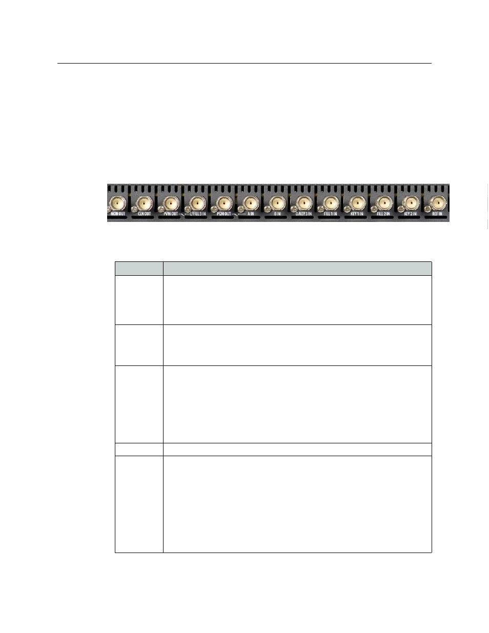
Fig. 12-2: Rear Panel Connectors - Video Inputs and Outputs
The following table lists the video signals, in order from left to right:
HD
1080i50, 720p50, 1080i59.94, 720p59.94
SD 625i50,
525i59.94
Name
Description
MON OUT
Video monitor output.
The Imagestore 750 allows you to monitor a number of internal signal paths through this
connector. You can monitor video throughout the system, from the inputs through to the
outputs (including between keyers) plus the contents of stores (fill and key), DVE scalers,
color fields and test patterns.
CLN OUT
Clean-feed output.
The Imagestore 750 allows you to view a number of internal signal paths through this
connector. The clean-feed output can be used to view partially branded video of the pro-
gram bus.
PVW OUT
Preview output.
The Imagestore 750 allows you to view a number of internal signal paths through this
connector. Graphics for each keying layer are shared between the program and preview
video buses, but keyer states are independent. The preview output is typically used for
previewing graphics, audio voice-overs, and DVE moves prior to bringing them to air on
the program bus.
Audio for program and preview can be controlled independently. This allows Easyplay
clips or external voice-overs to be previewed before being heard on the program output.
C/FILL-3 IN
Key 3’s fill input. This signal is also called ‘C IN’.
PGM OUT
Program output.
The signal on this connector is the output generated by the Imagestore 750: a combina-
tion of an input video signal with any graphics that are keyed onto the program bus, plus
embedded audio output from the audio mix engine.
An exception to this is when a test pattern is routed directly to PGM OUT, which is only
useful for commissioning purposes.
Whenever the Imagestore 750’s software is inactive, a bypass relay on the rear panel con-
nects A IN directly to PGM OUT (and C IN directly to PVW OUT). This ensures that input
video always gets to air, although the Imagestore 750 loses its ability to key graphics at
this time.
Table 12-1: Video Connectors Inputs and Outputs