Monitor wall configuration – Grass Valley Imagestore 750 v.3.0.1 User Manual
Page 111
95
Imagestore 750
User Manual
Monitor Wall Configuration
As an iMC panel acquires an Imagestore 750, the following can be displayed on the panel’s
monitor wall:
•
Program output.
•
Preset (a.k.a. preview) output.
•
Clean-feed output.
•
Monitor output.
•
Aux output.
•
User 1–20.
in addition to the sources in the current source group.
Open the MCS Panel Configuration Editor, choose a panel, and then go to the ‘Monitor Wall’
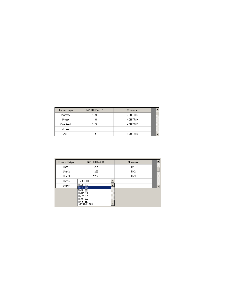
page. Use the channel output list. The first 5 entries in the list represent Imagestore 750 outputs:
Fig. 5-39: IiMC-Panel Configuration tool - Monitor Wall Channels, Imagestore 750 outputs
The remaining entries
—
when you scroll down
—
represent the sources identified as User-1
through User-20:
Fig. 5-40: IiMC-Panel Configuration tool - Monitor Wall Channels, User outputs
Assign NV9000 destination IDs for each channel output that you want to appear on this panel’s
monitor wall.
All the NV9000 destinations (i.e., router outputs) you choose here must, of course, be physi-
cally connected to the same monitor wall.
It is easier to make these assignments when the MCS Panel Configuration Editor is
“attached” to the NV9000 system. Check the appropriate box on the ‘NV9000 Settings’ page.
When the panel operator acquires a new channel, the panel causes appropriate router switches
so that the monitor wall shows the channel outputs, the aux output, and any user-defined
sources you have selected. The router sources associated with the Imagestore 750’s outputs and
the router sources labeled User-1 through User-20 must also have been configured for each
Imagestore 750 this panel will control. Please see
on page 85 for details.
Typically, the monitor wall
displays outputs from the
Imagestore 750 that is
currently owned by the
panel, and can also
display custom outputs
such as a backup channel.
The router destinations
configured here are used
for these purposes.