Features, Dve inserted after keyer 1 – Grass Valley Imagestore 750 v.3.0.1 User Manual
Page 58
42
Features
DVE (for Program and Preview)
•
DVE inserted after keyer 1
•
DVE inserted after keyer 2
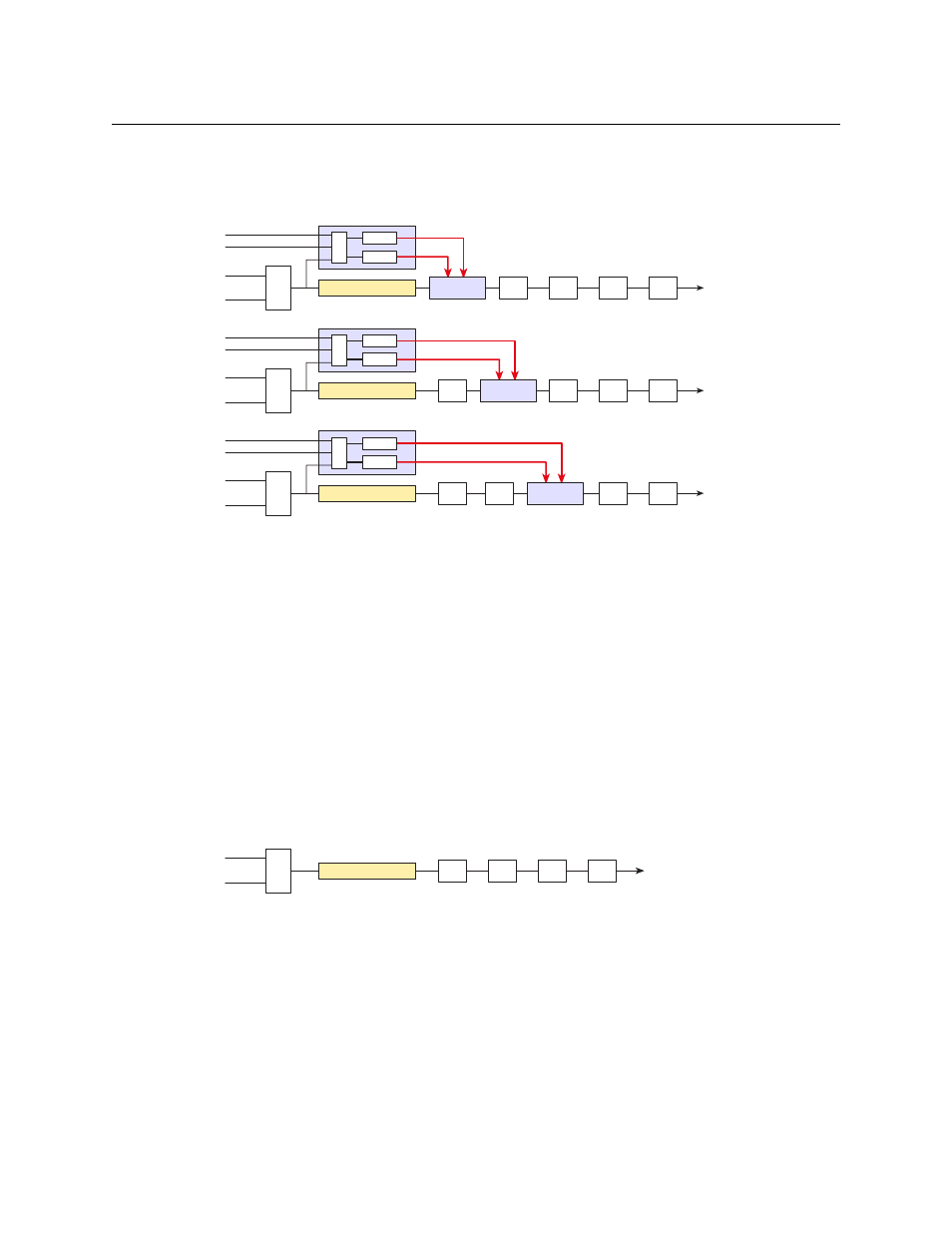
This diagram illustrates the 3 DVE configuration options:
Fig. 4-8: DVE insert positions:- before keyers; after keyer 1; after Keyer 2
Each heavy (red) line represents a fill/key signal from one of the DVE scalers, which is then keyed
over the background video at a position that depends on the current DVE configuration.
When DVE mode is enabled, the DVE keyer will often present full-screen video (normally routed
from the A/B mixer). Any DSKs that are upstream of the DVE keyer will be lost. However, it is
normal to have at least one DSK upstream of the DVE keyer so that full-screen media graphics
can be used to hide the background video coming through the compensating delay. These
graphics will also be revealed when the DVE squeezes back from full screen.
Note: The relative positioning of DVE1 and DVE2 scalers can also be modified using the DVE
sequence editing software.
When DVE mode is disabled, the background video continues to pass through the compen-
sating video delay. The compensating delay must be set to match the delay through the DVE
scalers exactly. That way, when DVE mode is re-enabled, there will be no glitch in the video
output.
Fig. 4-9: DVE video compensating delay
B
A
A/B
Mix
DSK1
DSK2
DSK3
DSK4
B
A
A/B
Mix
DSK1
DSK2
DSK3
DSK4
B
A
A/B
Mix
DSK2
DSK3
DSK4
Comp. Delay
DVE 1
DVE 2
Comp. Delay
Comp. Delay
DVE Keyer
DSK1
MUX
DVE 1
DVE 2
DVE 1
DVE 2
MUX
MUX
DVE Keyer
DVE Keyer
B
A
A/B
Mix
DSK1
DSK2
DSK3
DSK4
Comp. Delay