Connection of general-purpose interface (gpi), Installation – Grass Valley Imagestore 750 v.3.0.1 User Manual
Page 224
208
Installation
Rear Panel and Connections
LTC+, LTC–, ground.
•
Total DC fail alarm.
2-pin “contact closure” for a condition of total DC voltage failure within the Imagestore 750.
(When the Imagestore 750 is normally powered, these 2 pins are isolated.) These contacts
can be used to switch on some external warning buzzer or lamp (provided this is less than
400
mA, and less than 25
V.
•
Dolby metadata RS-485 serial ports.
4 ports (4 differential signals) configured as input or output.
115200 Baud.
1 start bit, 8 data bits, 1 stop bit, no parity
•
Two RS-232 ports for future use.
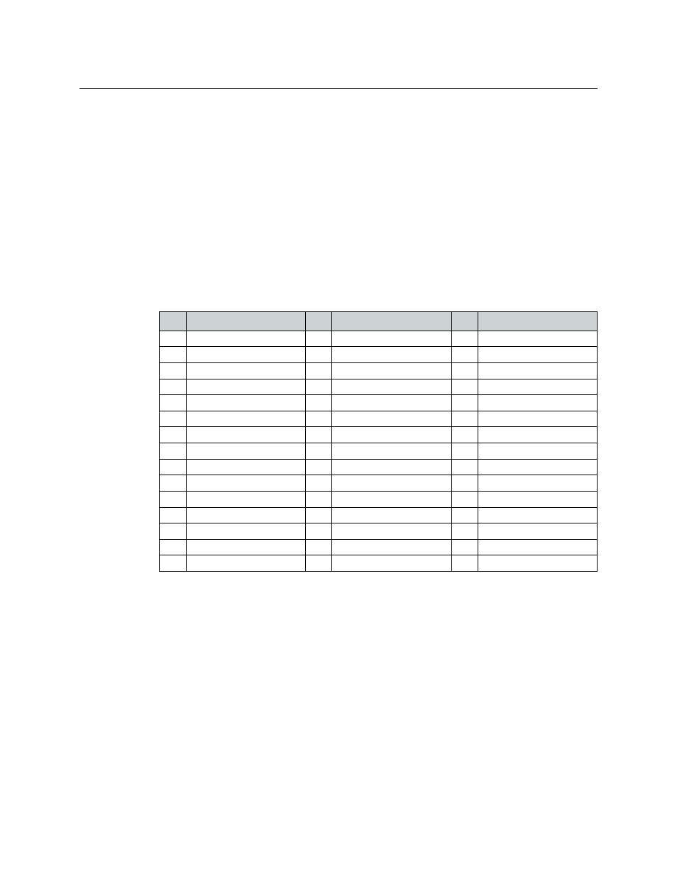
The table below shows pin-outs for the GPIO 44-way D-type connector.
Note: GPI numbering is zero-based for pin-outs, automation, and the front panel. (Use GPI-0,
GPI-1, GPI-2, and so on, to GPI-15.)
Miranda offers a 44-terminal GPIO adapter to help you use this connector. Its order code is
GPIO-
44TBA
. Another adapter is the IS-25-44-ADP, which is a 25-pin-to-44-pin adaptor that allows
wiring designed for the 25-pin GPI/LTC connector to be used with the 44-pin GPI/LTC connector.
Note: The 25-pin GPIO/LTC port was used with earlier Imagestore 750s. Please refer to the
Imagestore 750 user’s manual for version 1.14.0 or 1.14.1 software.
Connection of General-Purpose Interface (GPI)
Any GPI port can be used either to trigger the execution of a series of internal pre-programmed
commands (input) or to monitor the status of the Imagestore 750 (output). Each GPI can be
configured as either an input or an output. See
General Purpose Interface (GPI)
Pin Signal Name
Pin Signal Name
Pin Signal Name
1
LTC–
16
RS485/1+
31
LTC+
2
LTC_GND
17
RS485/1–
32
GP_GND
3
TOTAL_DC_FAIL
18
RS485/2+
33
GPIO_15
4
GPIO_14
19
RS485/2–
34
GPIO_13
5
GPIO_12
20
RS485/3+
35
GPIO_11
6
GPIO_10
21
RS485/3–
36
GPIO_9
7
GP_+5V
22
RS485/4+
37
TOTAL_DC_FAIL
8
GP_+12V
23
RS485/4–
38
GPIO_8
9
GPIO_7
24
GND
39
GPIO_6
10
GPIO_5
25
GND
40
GPIO_4
11
GPIO_3
26
GND
41
GPIO_2
12
GPIO_1
27
RS232A_TX (reserved)
42
GPIO_0
13
GP_GND
28
RS232A_CTS (reserved)
43
RS232A_RX (reserved)
14
RS232B_TX (reserved)
29
RS232A_RTS (reserved)
44
RS232B_RX (reserved)
15
RS232B_RTS (reserved)
30
RS232B_CTS (reserved)
Table 12-6: GPIO / LTC connector pinouts