Touchscreen display, Control panel – Grass Valley iMC-Panel-100 v.7.2.9.0 User Manual
Page 58
46
Control Panel
Connectors
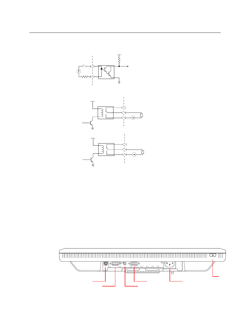
If you intend to use any of these connections, make the connections according to figures 3-10
and two diagrams.
Figure 3-10. GPI Input
Fig. 3-11: GPI Output andAlarms
Power applied to the inputs can be from 5 to 24 VDC, and less than 30 mA. Typically, 5 V at 1 mA.
Loads for the outputs can be larger:
Max current:
1 A
Max voltage:
125 VAC, 110 VDC.
Max capacity:
62.5 VA, 33 W.
Rated loads:
1 A at 30 VDC; 0.3 A at 110 VDC; 0.5A at 125 VAC.
Touchscreen Display
This describes the Planar PT1945R touchscreen display. If you have purchased another display
type, the connections will differ.)
At the bottom of the Planar touchscreen display (in a recess) are an AC power connector, a VGA
connector, an RS232 connector, a 3 mm audio jack, and a USB connector:
+3.3V
Optical
Isolation
C
E
GPI Input n
to internal bus
10K
Customers
Circuit
+
If your GPI input cable has a ground wire or
shielding, you can connect the ground (or
shielding) to the associated ground pin on
the DB25 connector. It is not necessary to do
so.
The ground pin is not shown here.
NO
NC
COM
+5V
from internal bus
GPI Output n
Customers
Load
alarm signal
Alarm Relay
NO
NC
COM
+5V
Customers
Load
The GPI relay and alarm relay
circuits are identical.
Note: it is the NO circuit that
closes when the GPI output or
alarm is turned on. You can use
the NC circuit as well.
USB
RS232
VGA
AUDIO
AC Input
VGA Port
Audio Jack
USB Port
RS-232 Port
On/Off
Switch