Main motor assembly – EXP Computer C4077-90960 User Manual
Page 172
Main Motor Assembly
1
Remove the back cover (see Figure 6-4).
2
Remove the HVPS (see Figure 6-40).
3
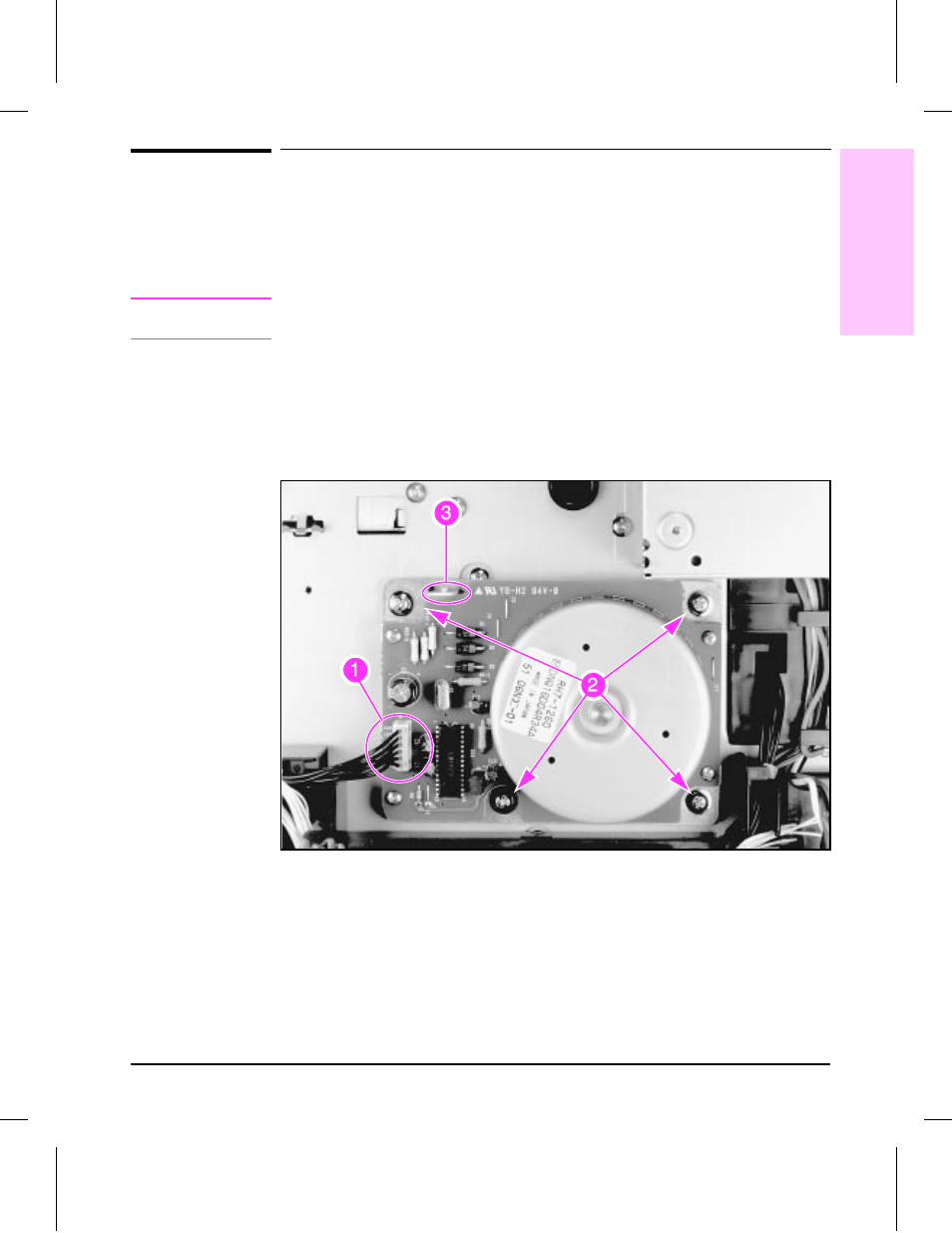
Unplug the connector (Figure 6-30, callout 1).
C a u t i o n
Be careful when removing the Main Motor. The steel drive shaft can
damage the plastic gears.
4
Remove (4) screws, CH103 (Figure 6-30, callout 2).
To Reinstall:
Align the Main Motor to the chassis with the locator tab (Figure 6-30,
callout 3), and the machined ring around the output shaft.
Main Motor
Figure 6-30
6
Removal and
Replacement
Removal and Replacement 6-45