3 implementation basics, 1 modes of transmission, 1 slave address field – RLE LD5200 V.2.3 User Manual
Page 86: 2 function field, 3 data field, Implementation basics, Modes of transmission, Slave address field function field data field, Figure 5.1 ld5200 connection diagram
86
LD5200 User Guide
800.518.1519
5
Modbus Communication
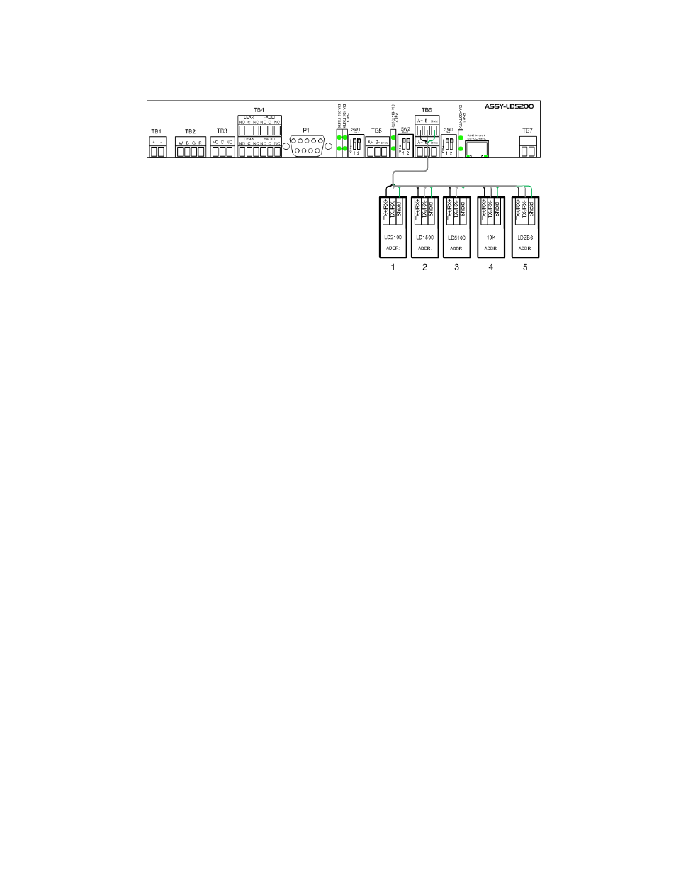
Figure 5.1 LD5200 Connection Diagram
5.3 Implementation
Basics
The LD5200 is capable of communicating via the half-duplex EIA-485 serial communication
standard. The EIA-485 medium allows for multiple devices on a multi-drop network.
5.3.1 Modes
of
Transmission
The Modbus protocol uses ASCII and RTU modes of transmission. The LD5200 supports only
the RTU mode of transmission, with 8 data bits, no parity and one stop bit. Every Modbus
packet consists of four fields:
♦
Slave Address Field
♦
Function Field
♦
Data Field
♦
Error Check Field (Checksum)
5.3.1.1 Slave
Address
Field
The slave address field is set by the going into local 160x160 display on the front panel. Go to
COMM PORT SETTINGS from the Main Menu screen. Select the Modbus Slave address and
the baud rate to be used for either/or EIA-485 Port1 and EIA-485 Port2.
5.3.1.2 Function
Field
The function field is one byte in length and tells the LD5200 which function to perform. The
supported functions are 03 (Read 4xxxx output registers), 04 (Read 3xxxx input registers), 06
(Preset single register) and 16 (Preset multiple registers).
5.3.1.3 Data
Field
The data field of the request is a variable length depending on the function. The data fields for
the LD5200 are 16-bit registers, transmitted high order byte first (big-endian).