Figure 2.2, Ld5200 physical connections and switches – RLE LD5200 V.2.3 User Manual
Page 17
rletech.com
LD5200 User Guide
17
2
Installation
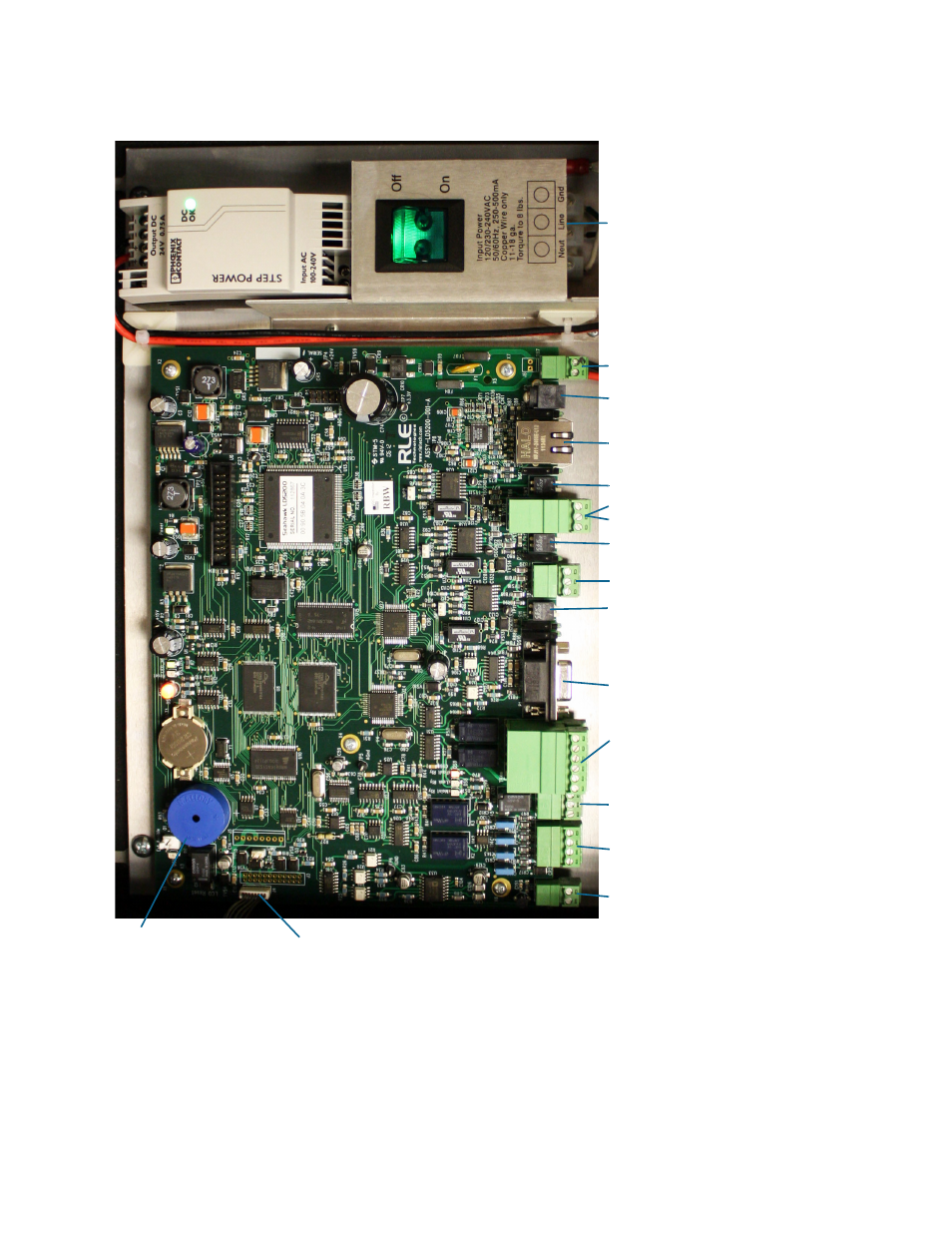
Figure 2.2
LD5200 Physical Connections and Switches
TB4 - (2) Form C Leak Relay Outputs
TB3 - Form C Maintenance Relay
TB1 - 4-20mA Output
TB2 - Cable Interface (W-B-G-R)
P1 - EIA-232 Connector
SW1 - EIA-485 Port 3 Termination
SW2 - EIA-485 Port 2 Termination
SW3 - EIA-485 Port 1 Termination
P2 - Ethernet Jack
TB7 - Input Power
TB5 - EIA-485 Port 3
TB6 Top - EIA-485 Port 1
TB6 Bottom - EIA-485 Port 2
SA1 - Audible Alarm
J4 - LCD Connection
P3 - Optional Power Connection
Power Input Terminal Block
(2) Form C Fault Relay Outputs
and