RLE F200 User Manual
F200 quick start guide, F200: rear connections and configuration button, Mount the controller
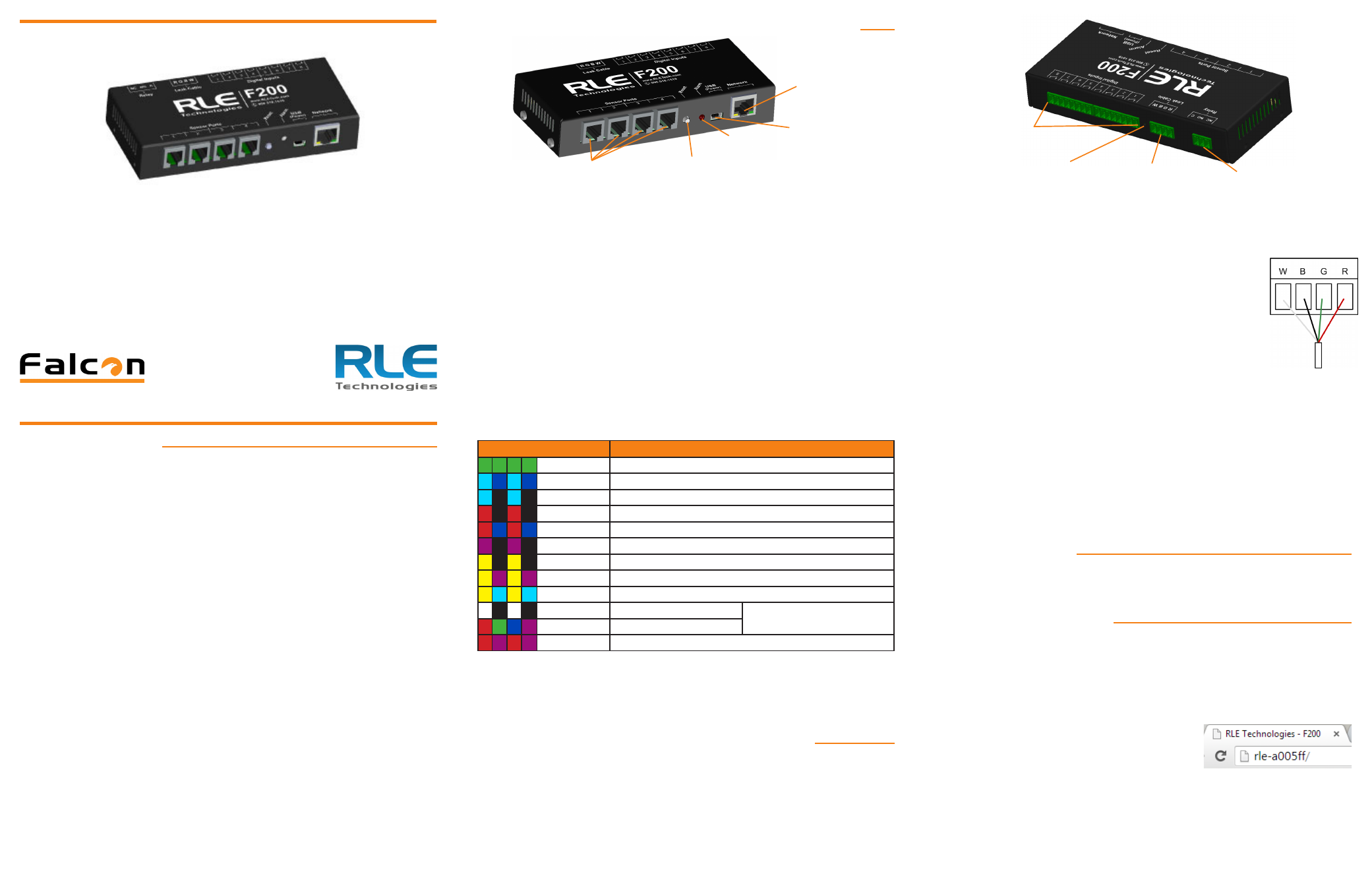
F200: Front Connections, Silence/Reset Button, and LED
1-Wire Sensor Connections
Plug in your temperature and temperature/humidity sensors. They click into place
in the sensor ports on the front of the unit.
Power Connection
The F200 is powered through its mini USB port. Using the included cable, plug the
mini end of the USB cable into the power jack on the F200. Plug the enclosed USB
wall charger into a standard wall outlet and plug the UBS cable into it. The F200
can also be powered by a USB connection on a server or another computer - just be
sure the computer is plugged into a wall outlet, preferably one protected by a UPS.
Network Connection
Plug the network cable into an available network port and then into the network
connection on the F200.
Status LED
There are a variety of alarm and alert patterns and colors programmed for the
F200’s LED. Use the following chart to determine which alarms are active.
Blink Pattern
Status Description
Solid Green
Normal status - no alarms are present
Lt. Blue/Blue
Alarm - Leak detection cable break
Lt. Blue/Off
Alarm - A leak has been detected
Red/Off
Alarm - Temperature
Red/Blue
Alarm - Humidity
Magenta/Off
Alarm - Digital input
Yellow/Off
No network connection
Yellow/Magenta Debug connection is active
Yellow/Lt. Blue
Configuration mode is active
White/Off
Unit is booting*
* Do not access or configure the
F200 while these alerts are active.
Mixed
Firmware update is executing*
Red/Magenta
Call RLE - the F200 has an internal error
Alarm Silence/Reset Button
If the audible alarm is active, push this button to silence it. Use the web interface
or LED to determine the alarm condition. Advanced functions are also assigned to
this button - consult the support section of RLE’s website for more information.
F200: Rear Connections and Configuration Button
Digital Inputs
The F200 can monitor eight digital inputs, each of which connects to the F200
through a 2-wire connection on the back of the unit. When you’re looking at the
back of the unit, note that input 1 is on the right side of the terminal blocks and
input 8 is on the left side of the terminal blocks.
To connect your digital inputs to the F200, loosen the screws on the appropriate
slots on the terminal block connector and insert the two wires from your digital
input - one in each slot. Tighten the screws to secure the connections.
Leak Detection Sensing Cable
Since leak detection sensing cable cannot connect directly to a controller, leader
cable is used to connect leak detection cable to the F200.
1. Remove the 4-pin terminal block connector from the back of the unit.
2. Insert the four stripped wires of the leader cable into the
appropriate slots in the terminal block connector - from left to
right: white, black, green, and red. Tighten the screws on the
terminal block connector to secure the leader cable. Plug the
connector - with the wires in the correct order - into the leak
detection leader cable connection.
3. Unscrew the EOL from the end of the leader cable.
4. Attach the length of sensing cable to the leader cable.
5. Route the sensing cable according to your cable layout diagram.
6. Secure the EOL to the unoccupied end of the sensing cable.
Relay Output
The F200 has one relay output - use this to control an external device in the event
of an alarm condition. Loosen the screws on the appropriate slots on the terminal
block connector and insert the wires for your relay output into the correct slots -
NC-NO-C. Tighten the screws to secure the connections.
Configuration Button
The configuration button is located on the back of the unit and is used for advanced
troubleshooting. Consult the support section of RLE’s website for more information.
Mount the Controller
Once all connections have been wired to the F200, mount the device in an
appropriate location. RLE recommends a secure mounting option, through either
the keyhole cutouts on the enclosure or through the optional 1U rack mount kit.
Establish Communications
Through DHCP, the F200 can be set up to communicate on your network.
**Please NOTE: If DHCP is not available on your network, the F200 will default to
an IP address of 10.0.0.188. If this is the case at your facility, skip steps 1-3, enter
the default IP address into your web browser address bar, and proceed to step 4.
1. Plug the enclosed network cable into an available network port, and then into
the Network connection on the F200. As soon as you plug the network cable
into the powered F200, DHCP assigns the F200 an IP address.
2. Using a computer running on the same subnet
as the F200, open a web browser. In the web
browser’s address bar, type rle-serialnumber/
where serial number is the actual serial number
of your F200 - for example, rle-a005ff/. Be sure to place the backslash
after the serial number. This will ensure the browser executes a DNS
lookup instead of a web search.
3. Press enter. The browser will find the newly installed F200 and allow you to
access the F200’s web interface.
4. You may either leave the IP address as it is or change it to an IP address
provided by your IT department. If you’d like to change the IP address, click
© Raymond & Lae Engineering, Inc. 2011. All rights reserved. RLE® is a registered trademark and Seahawk™, Falcon™, and Raptor™ are trademarks
of Raymond & Lae Engineering, Inc. The products sold by Raymond & Lae Engineering, Inc. are subject to the limited warranty, limited liability, and
other terms and conditions of sale set forth at http://rletech.com/RLE-Terms-and-Conditions.html.
v2.8
(06/2014)
Installation Supplies
Included with the F200
F200 device
Network cable
USB cable; USB mini B to USB A
5V USB wall wart
Available from RLE, sold separately
Temperature sensors
Temperature/humidity sensors
Conductive fluid or chemical sensing cable, plus leader cable kit and EOL terminator
1U rack mount kit
Network Communications Information
The F200’s serial number is found on the back of the unit, on a small white sticker
located under the connections for the digital inputs.
• F200 Serial Number________________________________________
Consult your IT administrator and determine the following network settings for your
F200:
• IP Address _______________________________________________
• Subnet Mask _____________________________________________
• Default Gateway __________________________________________
** Wire all connections, sensors, and power to the F200 first - then access the
web interface to configure the device and designate parameters and notification
methods for your wired sensors, inputs, and relays.
F200 Quick Start Guide
Thank you for purchasing a Falcon F200. This guide describes how to install and
configure your unit.
If you need further assistance, please access the F200 support page on our
web site, email our support staff directly - [email protected], or call us at
800.518.1519.
Network
Connection
Power
Connection
1-Wire Sensor
Connections
Status
LED
Silence/Reset
Button
Leak Detection
Leader Cable
Connection
Relay
Output
Digital Input
Connections
Configuration
Button