8 map, Figure 4.13 leak detection reference map – RLE LD5200 V.2.3 User Manual
Page 60
60
LD5200 User Guide
800.518.1519
4
Web Interface
4.3.8 Map
The LD5200 allows users to upload up to 10 maps of their facilities and populate them with
leak detection data. This provides users with a real-time view of their facility, including the
physical location and status of their leak detection equipment, and a visual indication of any
active alarms.
Through the mapping process, the LD5200 creates an overlay for an uploaded map image. It
superimposes the locations of your equipment - based on coordinates you designate - over the
top of your map image. Once uploaded and populated, the map is accessible through the
buttons generated on the right side of the LD5200 home page.
Do not attempt to map your facility until your monitoring area is completely assembled - all of
your leak detection equipment is in place, tested, and functional.
You’ll need a map of your facility. You can draw maps yourself, or RLE can create maps from
sketches or mechanical drawings that you provide. When creating your own map and image
file, keep in mind that the image file must be:
♦
500kb or less in size
♦
4000 x 4000 pixels or less
♦
A .jpg, .jpeg, .bmp, .gif, or .png formatted file.
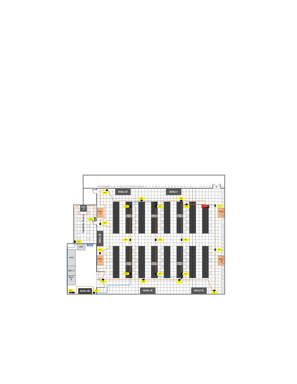
Figure 4.13
Leak Detection Reference Map
A .pdf or .vsd image can be uploaded to the LD5200, but .pdf and .vsd files do not support the
interactive mapping overlays. Upload .pdf and .vsd files for visual reference only.
Since the LD5200 never actually edits your map, if you should need to update your map
image, previously designated map points will not need to be reconfigured. As long as you do
not change size of your map, previously mapped coordinates should not need to be adjusted
when you upload a new version of your map.