RLE LD1000 User Manual
Seahawk ld1000 quick start guide
© Raymond & Lae Engineering, Inc. 2011. All rights reserved. RLE® is a registered trademark and Seahawk™, Falcon™, and Raptor™ are
trademarks of Raymond & Lae Engineering, Inc. The products sold by Raymond & Lae Engineering, Inc. are subject to the limited warranty, limited
liability, and other terms and conditions of sale set forth at http://rletech.com/RLE-Terms-and-Conditions.html.
Supplies for Installation
Included with the LD1000
15 foot (4.57m) leader cable
End-of-line terminator (EOL)
Wall mounting hardware
Available from RLE, sold separately
SeaHawk sensing cable, up to 1000 feet (305m)
Power supply: 24VDC (PSWA-DC-24) or 24VAC (WA-AC-24)
Mount the Device
The LD1000 is a wall mounted device, and mounting hardware is supplied with
every unit.
1. Select a location for the LD1000 and place the two screw anchors in the wall
4.25 inches (107.9mm) apart.
2. Screw both screws into the wall anchors so that approximately 1/8 inch
(3.18mm) of each screw is showing. It may be necessary to adjust the
screws—in or out—so that the unit fits snugly to the wall.
3. Remove the front cover from the LD1000 and hang the rear of the unit on
the screws.
4. Pull the unit toward the ground, so the screws nestle in the top of each
keyhole, and securely fasten the unit to the wall.
** As you wire and configure the LD1000, Refer to Figure A on the back of this page for a
detailed diagram of the device’s internal circuit board and wiring connections. **
Connect the Sensing Cable
Leader cable is used to connect sensing cable to the LD1000, since sensing cable
cannot connect directly to the device.
1. Remove the appropriate circular knockout from the enclosure and thread the
end of the leader cable through the knockout.
2. Insert the four stripped wires of the leader cable into the appropriate slots in
the Cable Input terminal block at the bottom right corner of the LD1000:
White wire: insert into pinout labeled W
Black wire: insert into pinout labeled B
Green wire: insert into pinout labeled G
Red wire: insert into pinout labeled R
3. Unscrew the EOL from the end of the leader cable.
4. Attach the length of sensing cable to the leader cable.
5. Route the sensing cable according to your cable layout diagram.
6. Secure the EOL to the unoccupied end of the sensing cable.
Connect the Relay Outputs
The LD1000 can be used as a stand-alone device, but it does have two Form
C relay outputs that communicate leak and fault status to another device or
system. If you wish to use the relay outputs, wire them at this time.
Connect the Power
The LD1000 requires an isolated 24VDC or 24VAC power supply. There
are separate terminal blocks for DC and AC power. To avoid product
damage and personal injury, wire power to the corresponding DC or AC terminal
blocks. Establish all wiring connections, including sensing cable, relay outputs,
and power before you activate the board’s power supply.
DIP Switch Settings
The LD1000 has four DIP switches. Adjust the switches to suit your application.
SW1-1
Configure the Relay Outputs as Supervised or Non-supervised
Off (default)
Relays are non-supervised - the relays remains OFF until an alarm is detected
- at which time the relays turns ON.
On
Relays are supervised - the relays remains ON until either power is disabled or
an alarm is detected - at which time the relays turn OFF.
SW1-2
Configure the Relay Outputs as Latching or Non-latching
Off (default)
Relays are non-latching - when an alarm is detected, the relays will remain in
alarm state until the Quiet/Test/Reset button is pushed, or until the condition
that caused the alarm returns to a normal state.
On
Relays are latching - when an alarm is detected, the relays will remain in
alarm state until the Quiet/Test/Reset button is pressed.
SW 1-3
Configure Relay Outputs as Two Summary Alarms or as Separate Leak and Fault Alarms
Off (default)
Relay one is a leak alarm; relay two is a fault alarm.
On
Both relay one and relay two are summary alarms.
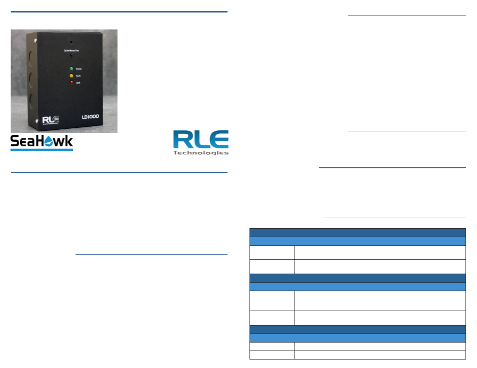
SeaHawk LD1000 Quick Start Guide
Thank you for purchasing
a SeaHawk LD1000 single-
zone leak detection controller.
This guide outlines device
installation and operation.
If you need further assistance,
please visit the support section
of our website - rletech.com -
or call us at 800.518.1519.
v2.1
(07/2014)