Adac get trigger structure – Measurement Computing ADAC-LVi User Manual
Page 201
Chapter 2 Trigger Config Library
ADAC LabVIEW VI
195
$'$& 6HW 3RVW 6DPSOH &RXQW FRQ¶W
error in (no error) Error in describes error conditions occurring before this VI executes.
This cluster defaults to no error.
Device Handle out Device Handle out contains the value of Device Handle in.
error out Error out contains error information. If the error in cluster indicated an error,
the error out cluster contains the same information. Otherwise, error out describes the
error status of this VI.
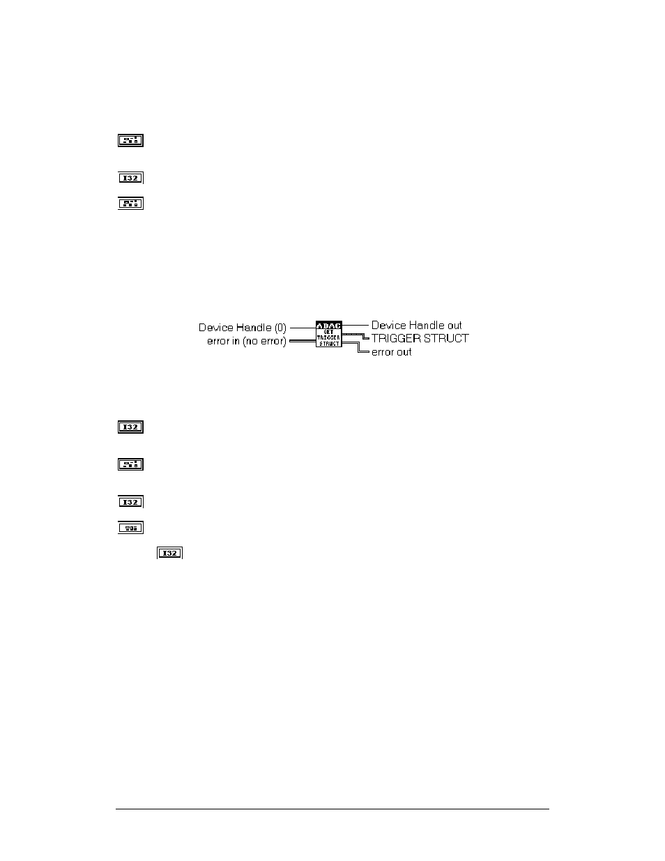
ADAC Get Trigger Structure
This VI provides access to the device trigger settings. See the associated trigger setting
VI for a full description of the TRIGGER STRUCT cluster.
Device Handle (0) Device Handle is a numeric value that is used to identify the device
subsystem. The default Device Handle is 0.
error in (no error) Error in describes error conditions occurring before this VI executes.
This cluster defaults to no error.
Device Handle out Device Handle out contains the value of Device Handle in.
TRIGGER STRUCT
Trigger Mode Trigger Mode is a numeric value that sets the hardware trigger
operation mode of the device. The available options are:
0:DISABLED All triggering is disabled
1:ABOUT_TRIG Collect (N) data points before and (N) data points after a
trigger
2:POST_TRIG Collect (N) data points after a trigger
3:PRE_TRIG Collect (N) data points before a trigger
4:SCAN_TRIG Collect 1 data point for each channel
The default Trigger Mode is 0:DISABLED