Ac power, Dc power, Tx if output connector (cp1) – Comtech EF Data SNM-1000 User Manual
Page 42: Rx if input connector (cp2), External reference (cp3), Ground connector (gnd), 6 ac power, 7 dc power, 8 tx if output connector (cp1), 9 rx if input connector (cp2)
SNM-1000 Node Control Modem
Revision 3
Installation
MN/SNM1000.IOM
2–10
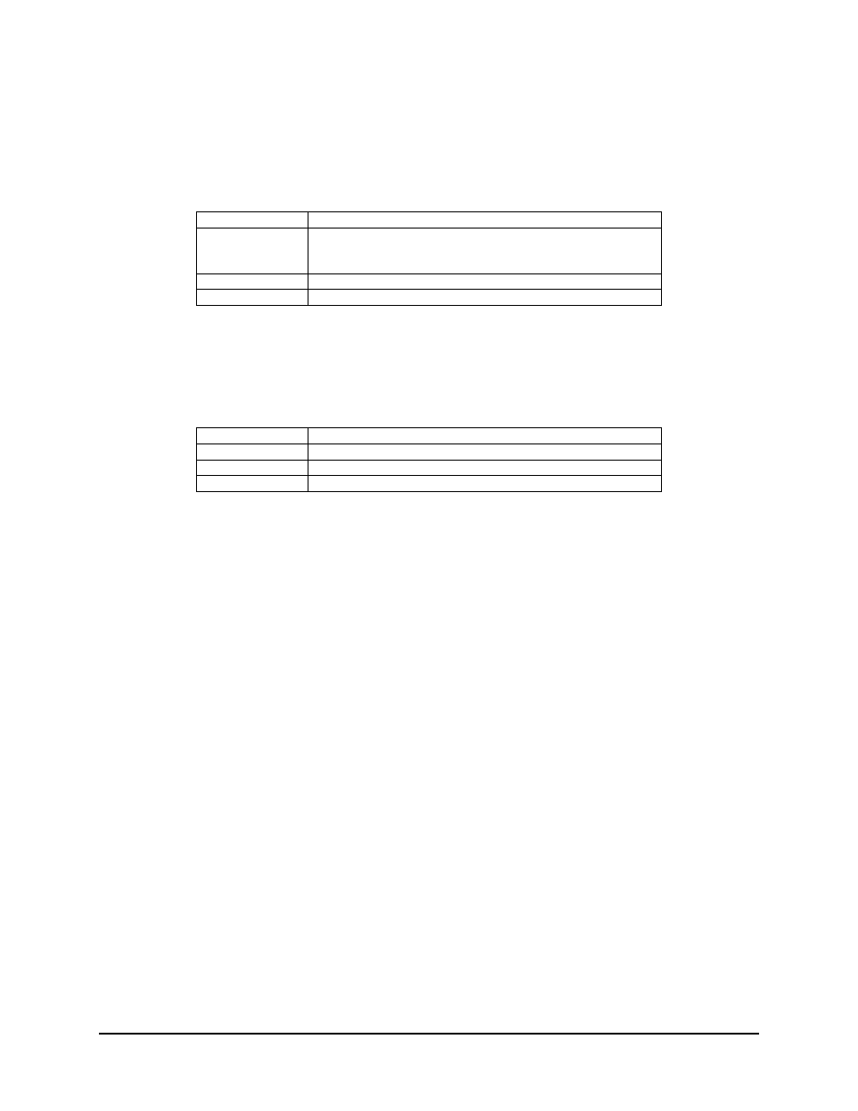
2.3.6 AC
Power
The AC power is supplied to the SNM-1000 by a standard, detachable, non-locking,
3-prong power cord. Refer to the following listing for AC power specifications.
Input power
50W max.
Input voltage
90 to 264 VAC, 47 to 63Hz.
Note: Unit switches ranges automatically.
Connector type
IEC
Fuse protection
1A slo-blo line and neutral fusing 5 mm type fuses.
2.3.7 DC
Power
For DC supplied units, the DC Power is supplied by terminal lugs installed on the back
panel. Refer to the following table for specifications
Input power
50W max.
Input voltage
38 to 64 VDC.
Connector type
Terminal Lug
Fuse protection
1A slo-blo 5 mm type fuses.
2.3.8
TX IF Output Connector (CP1)
CP1 is a BNC connector for the transmit IF signal. The standard output impedance is
75
Ω (50 Ω optional ), and the output power level is -5 to -30 dBm. In normal operation, the
output will be a 8PSK, QPSK/OQPSK, or BPSK-modulated result of the data connector
between 50 and 180 MHz, in 1 Hz steps.
2.3.9
RX IF Input Connector (CP2)
CP2 is a BNC connector for the RX-IF signal. The standard input impedance is
75
Ω (50Ω optional). For normal operation, the desired carrier signal level should be
between -30 and -55 dBm. Signals between 50 and 180 MHz are selected and demodulated
to produce clock and data.
2.3.10
External Reference (CP3)
CP3 is a BNC connector for an EX REF. The input impedance is 75
Ω.For normal
operation, the reference signal is
≥
0 dBm.
2.3.11
Ground Connector (GND)
A #10-32 stud on the rear panel of the modem is used for connecting a common chassis
ground among all equipment. The AC power connector provides the safety ground.