Auxiliary 1 connector and pinouts (j9), 4 auxiliary 1 connector and pinouts (j9) – Comtech EF Data SNM-1000 User Manual
Page 40
SNM-1000 Node Control Modem
Revision 3
Installation
MN/SNM1000.IOM
2–8
2.3.4
Auxiliary 1 Connector and Pinouts (J9)
The auxiliary 1 (AUX 1) connector provides:
• MOD and DEMOD (TTL) faults
• Satellite
clock
• Satellite
I&Q
• Automatic Gain Control (AGC) output voltage
The faults are open collector levels that indicate a modulator or demodulator failure. A logic
“1” indicates the faulted condition.
AGC_OUT is a programmable voltage, 0 to 10V, for a receive signal level between -25 and
-60 dBm.
AUX 1 connection is a 9-pin female D connector (J9) located on the rear panel of the
modem. Screw locks are provided for mechanical security on the mating connector. Refer to
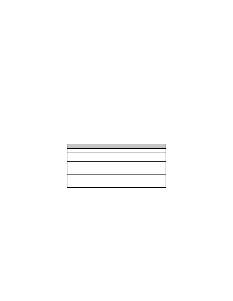
Table 2-4 for pinout information
Table 2-4. AUX 1 Connector and Pinouts (J9)
Pin #
Signal Function
Name
1
Satellite Clock -
SAT_CLK-
2 No
Connection
NC
3
Satellite Clock +
SAT_CLK+
4
MODULATOR TTL Fault
MDFLTTTL
5 Ground
GRN
6
RX Q Channel Eye
RX_Q
7
DEMODULATOR TTL Fault
DFFLTTTL
8
RX 1 Channel Eye
Rx_1
9
Agc Output
AGC