Retriggerable input mode, Cascading counter/timers, Figure 84 – Zilog Z86193 User Manual
Page 98
Z8
®
CPU
User Manual
UM001604-0108
Counters and Timers
91
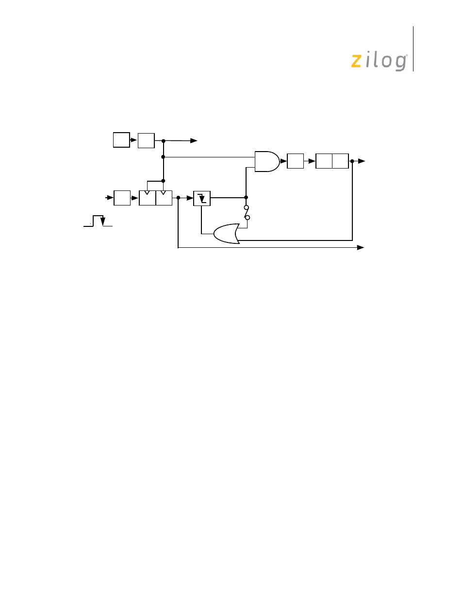
T1 is triggered counting continues until software resets the Enable Count bit. Interrupt
request IRQ5 is generated when T1 reaches its end-of-count.
Retriggerable Input Mode
The T
IN
Retriggerable Input Mode (TMR bits 5 and 4 are set to 1) causes T1 to load and
start counting on every occurrence of a High-to-Low transition on T
IN
Interrupt request IRQ5 is generated if the programmed time interval (determined by T1
prescaler and counter/timer register initial values) has elapsed because of the last High-to-
Low transition on T
IN
. In SINGLE-PASS Mode, the end-of-count resets the Enable Count
bit. Subsequent T
IN
transitions do not cause T1 to load and start counting until software
sets the Enable Count bit again. In Continuous Mode, counting continues once T1 is trig-
gered until software resets the Enable Count bit. When enabled, each High-to-Low T
IN
transition causes T1 to reload and restart counting. Interrupt request IRQ5 is generated on
every end-of-count.
Cascading Counter/Timers
For some applications, it may be necessary to measure a time interval greater than a single
counter/timer can measure. In this case, T
IN
and T
OUT
can be used to cascade T0 and T1
as a single unit (see
on page 92). T0 should be configured to operate in Continu-
ous mode and to drive T
OUT
. T
IN
should be configured as an external clock input to T1
and wired back to T
OUT
. On every other T0 end-of-count, T
OUT
undergoes a High-to-Low
transition that causes T1 to count.
T1 can operate in either Single-Pass or Continuous mode. When the T1 end-of-count is
reached, interrupt request IRQ5 is generated. Interrupt requests IRQ2 (T
IN
High-to-Low
transitions) and IRQ4 (T0 end-of-count) are also generated but are most likely of no
importance in this configuration and should be disabled.
Figure 84. Triggered Clock Mode
OSC
÷
2
÷
4
D
D
PRE1
TMR
P3
1
T1
IRQ
2
T
IN
IRQ
5
Trigger
D
5
–D
4 =
11
Internal
TMR
D
5 =
1
Clock
Edge
Trigger
- Z86233 Z86243 Z86733 Z86743 Z86C02 Z86C04 Z86C08 Z86C15 Z86C21 Z86C30 Z86C31 Z86C33 Z86C36 Z86C40 Z86C43 Z86C61 Z86C62 Z86C63 Z86C65 Z86C83 Z86C90 Z86C91 Z86C93 Z86C96 Z86E02 Z86E03 Z86E04 Z86E06 Z86E07 Z86E08 Z86E15 Z86E21 Z86E30 Z86E31 Z86E33 Z86E34 Z86E40 Z86E43 Z86E44 Z86E61 Z86E63 Z86E83 Z86K15 Z86L02 Z86L04 Z86L08 Z86L16 Z8E000 Z8E001 Z8PE003