Gated internal clock mode, Triggered input mode, Gated internal clock mode triggered input mode – Zilog Z86193 User Manual
Page 97: Cpu user manual, The t, See figure 83 ). t1 counts while t, Is high and stops counting while t, Input. subsequent t
Z8
®
CPU
User Manual
UM001604-0108
Counters and Timers
90
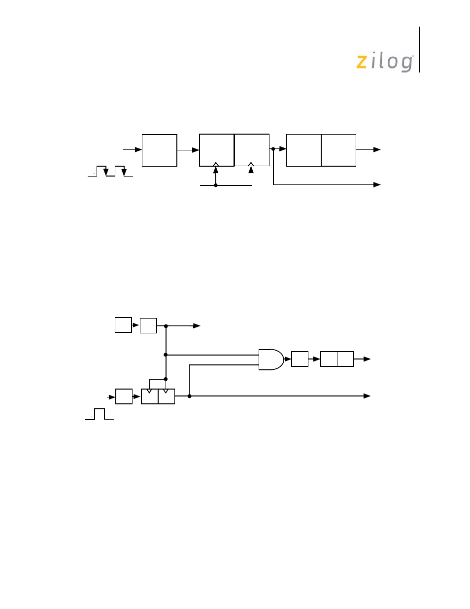
Gated Internal Clock Mode
The T
IN
Gated Internal Clock Mode (TMR bit 5 and bit 4 set to 0 and 1 respectively) mea-
sures the duration of an external event. In this mode, the T1 prescaler is driven by the
internal timer clock, gated by a High level on T
IN
IN
is
High and stops counting while T
IN
is Low. Interrupt request IRQ2 is generated on the
High-to-Low transition of T
IN
signalling the end of the gate input. Interrupt request IRQ5
is generated if T1 reaches its end-of-count.
Triggered Input Mode
The T
IN
Triggered Input Mode (TMR bits 5 and 4 are set to 1 and 0, respectively) causes
T1 to start counting as the result of an external event (see
on page 91). T1 is then
loaded and clocked by the internal timer clock following the first High-to-Low transition
on the T
IN
input. Subsequent T
IN
transitions do not affect T1. In SINGLE-PASS mode, the
Enable bit is reset whenever T1 reaches its end-of-count. Further T
IN
transitions have no
effect on T1 until software sets the Enable Count bit again. In CONTINUOUS mode, once
Figure 82. External Clock Input Mode
Figure 83. Gated Clock Input Mode
D
P3
1
Internal
IRQ
2
TMR
T
IN
Clock
D
PRE1
T1
IRQ
5
D
5
–D
4
= 00
Clock
OSC
÷
2
÷
4
D
D
PRE1
P3
1
T1
IRQ
2
T
IN
IRQ
5
Gate
Internal
TMR
D
5–
D
4 =
01
Clock
- Z86233 Z86243 Z86733 Z86743 Z86C02 Z86C04 Z86C08 Z86C15 Z86C21 Z86C30 Z86C31 Z86C33 Z86C36 Z86C40 Z86C43 Z86C61 Z86C62 Z86C63 Z86C65 Z86C83 Z86C90 Z86C91 Z86C93 Z86C96 Z86E02 Z86E03 Z86E04 Z86E06 Z86E07 Z86E08 Z86E15 Z86E21 Z86E30 Z86E31 Z86E33 Z86E34 Z86E40 Z86E43 Z86E44 Z86E61 Z86E63 Z86E83 Z86K15 Z86L02 Z86L04 Z86L08 Z86L16 Z8E000 Z8E001 Z8PE003