Prescaler operations – Zilog Z86193 User Manual
Page 91
Z8
®
CPU
User Manual
UM001604-0108
Counters and Timers
84
The counter timers remain at rest as long as the Enable Count bits are 0. To enable count-
ing, the Enable Count bit (D
1
for T0 and D
3
for T1) must be set to 1. Counting actually
starts when the Enable Count bit is written by an instruction. The first decrement occurs
four internal clock periods after the Enable Count bit has been set. If T1 is configured to
use an external clock, the first decrement begins on the next clock period. The Load and
Enable Count bits can be set at the same time. For example, using the instruction:
OR TMR,#03h
sets both D0 and D1 of the TMR. This loads the initial values of PRE0 and T0 into their
respective counters and starts the count after the M2T2 machine state after the operand is
fetched (see
).
Prescaler Operations
During counting, the programmed clock source drives the 6-bit Prescaler Counter. The
counter is counted down from the value specified by bits of the corresponding Prescaler
Register, PRE0 (bit 7 to bit 2) or PRE1 (bit 7 to bit 2; see
Figure 74. Starting The Count
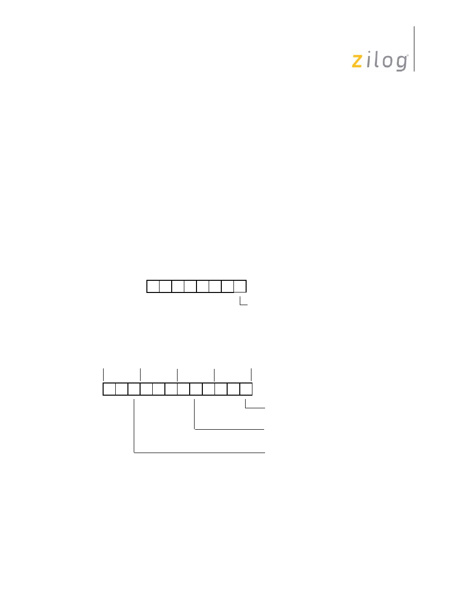
Figure 75. Counting Modes
D0
(% F5; Write-Only)
Count Mode
Prescaler 0 Register
R245 PRE0
(% F3; Write-Only)
Prescaler 1 Register
R243 PRE1
0 = T
1
Single Pass
1 = T
1
Modulo-n
T1 T2 T3 T1 T2 T3 T1 T2 T3 T1 T2 T3
TMR is Written, Counter/Timer
First Decrement Occurs
Four Clock Periods Later
is Loaded
#03h is Fetched
M3 M1 M2 Mn
- Z86233 Z86243 Z86733 Z86743 Z86C02 Z86C04 Z86C08 Z86C15 Z86C21 Z86C30 Z86C31 Z86C33 Z86C36 Z86C40 Z86C43 Z86C61 Z86C62 Z86C63 Z86C65 Z86C83 Z86C90 Z86C91 Z86C93 Z86C96 Z86E02 Z86E03 Z86E04 Z86E06 Z86E07 Z86E08 Z86E15 Z86E21 Z86E30 Z86E31 Z86E33 Z86E34 Z86E40 Z86E43 Z86E44 Z86E61 Z86E63 Z86E83 Z86K15 Z86L02 Z86L04 Z86L08 Z86L16 Z8E000 Z8E001 Z8PE003