Counter/timer operation, Load and enable count bits, Figure 72 – Zilog Z86193 User Manual
Page 90
Z8
®
CPU
User Manual
UM001604-0108
Counters and Timers
83
Counter/Timer Operation
Under software control, counter/timers are started and stopped via the Timer Mode Regis-
ter (TMR,
F1h
) bits D0–D3 (see
). Each counter/timer is associated with a Load
bit and an Enable Count bit.
Load and Enable Count Bits
Setting the Load bit (D0 for T0 and D2 for T1) transfers the initial value in the prescaler
and the counter/timer registers into their respective down-counters. The next internal
clock resets bits D0 and D2 to 0, readying the Load bit for the next load operation. New
values may be loaded into the down-counters at any time. If the counter/timer is running, it
continues to do so and starts the count over with the new value. Therefore, the Load bit
actually functions as a software re-trigger.
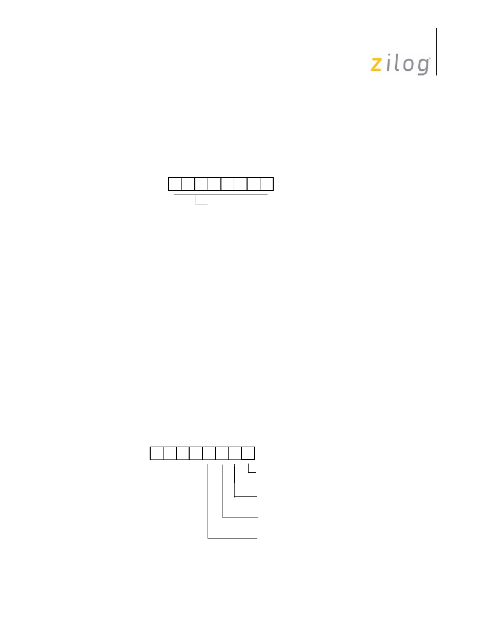
Figure 72. Counter/Timer 0 and 1 Registers
Figure 73. Timer Mode Register
D7 D6 D5 D4 D3 D2 D1 D0
(%F4; Write/Read Only)
current value when read
Initial value when written
(Range 1-256 decimal, 01-00 HEX)
Counter/Timer 0 Register
R244 T0
(%F2; Write/Read Only)
Counter/Timer 1 Register
R242 T1
D3 D2 D1 D0
(% F1; Read/Write)
0 = Disable T
0
Count
0 = No Function
1 = Load T
0
Timer Mode Register
R241 TMR
1 = Enable T
0
Count
0 = No Function
1 = Load T
1
0 = Disable T
1
Count
1 = Enable T
1
Count
- Z86233 Z86243 Z86733 Z86743 Z86C02 Z86C04 Z86C08 Z86C15 Z86C21 Z86C30 Z86C31 Z86C33 Z86C36 Z86C40 Z86C43 Z86C61 Z86C62 Z86C63 Z86C65 Z86C83 Z86C90 Z86C91 Z86C93 Z86C96 Z86E02 Z86E03 Z86E04 Z86E06 Z86E07 Z86E08 Z86E15 Z86E21 Z86E30 Z86E31 Z86E33 Z86E34 Z86E40 Z86E43 Z86E44 Z86E61 Z86E63 Z86E83 Z86K15 Z86L02 Z86L04 Z86L08 Z86L16 Z8E000 Z8E001 Z8PE003