Read/write operations, Handshake operation, Read/write operations handshake operation – Zilog Z86193 User Manual
Page 54: Figure 31
Z8
®
CPU
User Manual
UM001604-0108
Input/Output Ports
47
Read/Write Operations
In the nibble I/O Mode, Port 0 is accessed as general-purpose register P0 (
00h
) with ERF
Bank set to 0. The port is written by specifying P0 as an instruction's destination register.
Writing to the port causes data to be stored in the port's output register.
The port is read by specifying P0 as the source register of an instruction. When an output
nibble is read, data on the external pins is returned. Under normal loading conditions this
is equivalent to reading the output register. However, for Port 0 outputs defined as open–
drain, the data returned is the value forced on the output by the external system. This may
not be the same as the data in the output register. Reading a nibble defined as input also
returns data on the external pins. However, input bits under handshake control return data
latched into the input register via the input strobe.
The Port 0–1 Mode resistor bits D1–D0 and D7–D6 are used to configure Port 0 nibbles.
The lower nibble (P00–P03) can be defined as inputs by setting bits D1 to 0 and D0 to 1,
or as outputs by setting both D1 and D0 to 0. Likewise, the upper nibble (P04–P07) can be
defined as inputs by setting bits D7 to 0 and D6 to 1, or as outputs by setting both D6 and
D7 to 0 (see
Handshake Operation
When used as an I/O port, Port 0 can be placed under handshake control by programming
the Port 3 Mode register bit D2 to 1. In this configuration, handshake control lines are
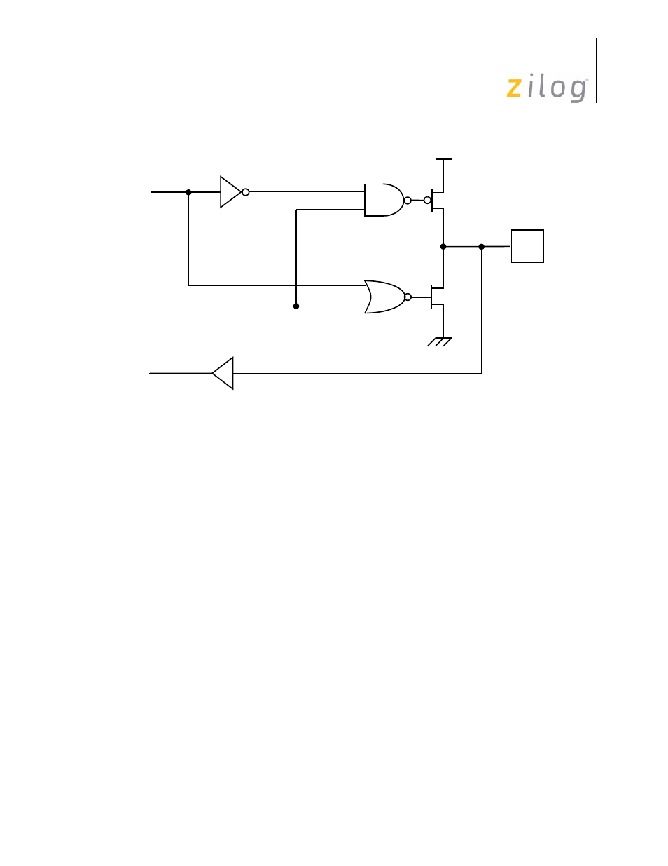
Figure 31. Port 0 Configuration with TTL Level Shifter
OEN
PIN
OUT
IN
TTL Level Shifter
- Z86233 Z86243 Z86733 Z86743 Z86C02 Z86C04 Z86C08 Z86C15 Z86C21 Z86C30 Z86C31 Z86C33 Z86C36 Z86C40 Z86C43 Z86C61 Z86C62 Z86C63 Z86C65 Z86C83 Z86C90 Z86C91 Z86C93 Z86C96 Z86E02 Z86E03 Z86E04 Z86E06 Z86E07 Z86E08 Z86E15 Z86E21 Z86E30 Z86E31 Z86E33 Z86E34 Z86E40 Z86E43 Z86E44 Z86E61 Z86E63 Z86E83 Z86K15 Z86L02 Z86L04 Z86L08 Z86L16 Z8E000 Z8E001 Z8PE003