Oscillator operation – Zilog Z86193 User Manual
Page 34
Z8
®
CPU
User Manual
UM001604-0108
Clock
27
Oscillator Operation
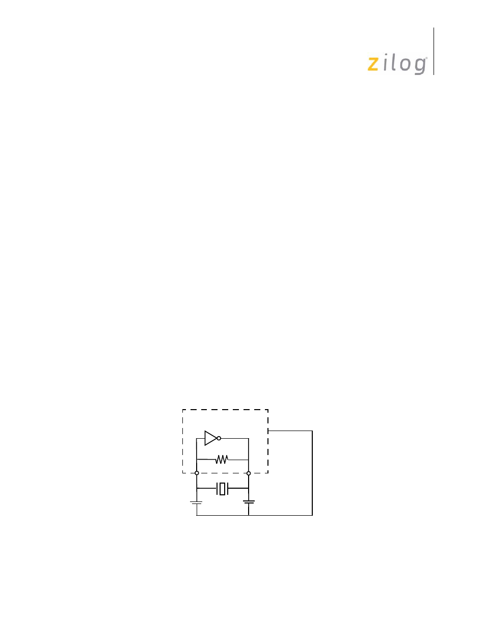
The Z8
®
CPU uses a Pierce oscillator with an internal feedback (see
advantages of this circuit are low cost, large output signal, low-power level in the crystal,
stability with respect to V
CC
and temperature, and low impedances (not disturbed by stray
affects).
One drawback is the requirement for high gain in the amplifier to compensate for feedback
path losses. The oscillator amplifies its own noise at start-up until it settles at the fre-
quency that satisfies the gain/phase requirements A x B = 1, where A = V
0
/V
I
is the gain of
the amplifier and B = V
I
/V
0
is the gain of the feedback element. The total phase shift
around the loop is forced to zero (360 degrees). Because VIN must be in phase with itself,
the amplifier/inverter provides 180 degree phase shift and the feedback element is forced
to provide the other 180 degrees of phase shift.
R1 is a resistive component placed from output to input of the amplifier. The purpose of
this feedback is to bias the amplifier in its linear region and to provide the start-up transi-
tion.
Capacitor C
2
combined with the amplifier output resistance provides a small phase shift. It
also provides some attenuation of overtones.
Capacitor C
1
combined with the crystal resistance provides additional phase shift.
C
1
and C
2
can affect the start-up time if they increase dramatically in size. As C
1
and C
2
increase, the start-up time increases until the oscillator reaches a point where it does not
start up any more.
For fast and reliable oscillator start-up over the manufacturing process range, Zilog
®
rec-
ommends that the load capacitors be sized as low as possible without resulting in overtone
operation.
Figure 16. Pierce Oscillator with Internal Feedback Circuit
XTAL2
Z8 CPU
V
SS
XTAL1
C1
C2
R
I
V
1
A
V
0
- Z86233 Z86243 Z86733 Z86743 Z86C02 Z86C04 Z86C08 Z86C15 Z86C21 Z86C30 Z86C31 Z86C33 Z86C36 Z86C40 Z86C43 Z86C61 Z86C62 Z86C63 Z86C65 Z86C83 Z86C90 Z86C91 Z86C93 Z86C96 Z86E02 Z86E03 Z86E04 Z86E06 Z86E07 Z86E08 Z86E15 Z86E21 Z86E30 Z86E31 Z86E33 Z86E34 Z86E40 Z86E43 Z86E44 Z86E61 Z86E63 Z86E83 Z86K15 Z86L02 Z86L04 Z86L08 Z86L16 Z8E000 Z8E001 Z8PE003