Autolatch model, Design considerations, Autolatch model design considerations – Zilog Z86193 User Manual
Page 85
Z8
®
CPU
User Manual
UM001604-0108
Input/Output Ports
78
second occurs when the input is connected to the output of a device with tri-state capabil-
ity.
The autolatch also activates when the input voltage at the pin is not within 200 microvolts
or so of either supply rail. In this case, the circuit draws current, which is not significant
compared to the I
CC
operating current of the device, but increases I
CC2
STOP mode cur-
rent of the device dramatically.
The fourth condition occurs when the I/O bit is configured as an output. As displayed in
on page 77, there are two ways of tri-stating the port pin. The first is by config-
uring the port as an input, which disables the OE signal turning both transistors OFF. The
second can be achieved in output mode by writing a 1 to the output port, then activating
the open-drain mode. Both transistors are again OFF, and the port bit is in a high imped-
ance state. The autolatches then pull the input section toward V
DD
.
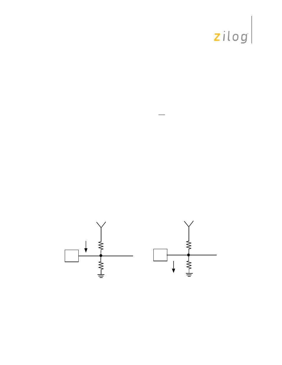
Autolatch Model
The autolatch’s equivalent circuit is displayed in
. When the input is high, the
circuit consists of a resistance Rp from V
DD
(the P-channel transistor in its ON state) and
a much greater resistance Rh to G
ND
. Current I
AO
flows from V
DD
to the output. When
the input is low, the circuit may be modeled as a resistance Rp from G
ND
(the N-channel
transistor in the ON state) and a much greater resistance Rh to V
DD
. Current I
AO
now
flows from the input to ground. The autolatch is characterized with respect to I
AO
, so the
equivalent resistance Rp is calculated according to R
P
= (V
DD
–V
IN
)/I
AO
. The worst case
equivalent resistance Rp (min) may be calculated at the worst case input voltage, V
I
= V
IH
(min).
Design Considerations
For circuits in which the autolatch is active, considerations should be given to the loading
constraints of the autolatches. For example, with weak values of V
IN
, close to Vih (min) or
Figure 66. Autolatch Equivalent Circuit
V
DD
Data in
PIN
Logic 1
A0
PIN
V
DD
R
P
R
H
R
H
R
P
Data in
Logic 0
A0
- Z86233 Z86243 Z86733 Z86743 Z86C02 Z86C04 Z86C08 Z86C15 Z86C21 Z86C30 Z86C31 Z86C33 Z86C36 Z86C40 Z86C43 Z86C61 Z86C62 Z86C63 Z86C65 Z86C83 Z86C90 Z86C91 Z86C93 Z86C96 Z86E02 Z86E03 Z86E04 Z86E06 Z86E07 Z86E08 Z86E15 Z86E21 Z86E30 Z86E31 Z86E33 Z86E34 Z86E40 Z86E43 Z86E44 Z86E61 Z86E63 Z86E83 Z86K15 Z86L02 Z86L04 Z86L08 Z86L16 Z8E000 Z8E001 Z8PE003