Cpu user manual – Zilog Z86193 User Manual
Page 71
Z8
®
CPU
User Manual
UM001604-0108
Input/Output Ports
64
the port is not protected and can be overwritten by the Z8 CPU during the handshake
sequence. To avoid losing data, the software must not overwrite the port until the corre-
sponding interrupt request indicates that the external device has latched the data.
The software can always read Port 3 output and input handshake lines, but cannot write to
the output handshake line.
The following is the recommended setup sequence when configuring a Port for handshake
operation for the first time after a reset:
•
Load P01M or P2M to configure the port for input/output
•
Load P3 to set the Output Handshake bit to a logic 1
•
Load P3M to select HANDSHAKE mode for the port
Once a data transfer begins, the configuration of the handshake lines should not be
changed until the handshake is completed.
and
on page 65 display detailed operation for the handshake
sequence.
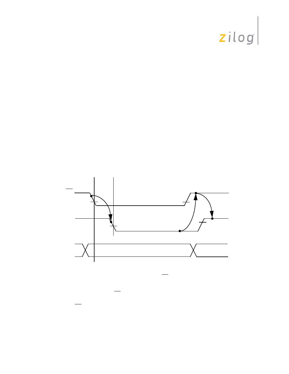
Figure 50. Z8 Input Handshake
Valid Data
(Input To Z8)
State 1.
2
1
3
4
5
DAV
Output From Z8)
RDY
(Input To Z8)
Data on Port
Port 3 output is High, indicating that the I/O device is ready to accept data.
State 2.
The I/O device puts data on the port and then activates the DAV input. This causes the data to be latched
.
State 3.
The Z8
®
CPU forces the Ready (RDY) output Low, signaling to the I/O device that the data has been latched.
State 4.
The I/O device returns the DAV line High in response to RDY going Low.
State 5.
The Z8
CPU RR software must respond to the interrupt request and read the contents of the port in order for the
into the port input register and generates an interrupt request.
handshake sequence to be completed. The RDY line goes High if and only if the port has been read and
DAV is High. This returns the interface to its initial state.
- Z86233 Z86243 Z86733 Z86743 Z86C02 Z86C04 Z86C08 Z86C15 Z86C21 Z86C30 Z86C31 Z86C33 Z86C36 Z86C40 Z86C43 Z86C61 Z86C62 Z86C63 Z86C65 Z86C83 Z86C90 Z86C91 Z86C93 Z86C96 Z86E02 Z86E03 Z86E04 Z86E06 Z86E07 Z86E08 Z86E15 Z86E21 Z86E30 Z86E31 Z86E33 Z86E34 Z86E40 Z86E43 Z86E44 Z86E61 Z86E63 Z86E83 Z86K15 Z86L02 Z86L04 Z86L08 Z86L16 Z8E000 Z8E001 Z8PE003