Zilog Z86193 User Manual
Page 94
Z8
®
CPU
User Manual
UM001604-0108
Counters and Timers
87
and bit 6 to 1 and 0, respectively. The counter/timer T
OUT
mode is turned off by setting
TMR bit and bit 6 both to 0, freeing P36 to be a data output line.
T
OUT
is initialized to a logic 1 whenever the TMR Load bit (bit 0 for T0 or bit 1 for T2) is
set to 1. The T
OUT
configuration timer load, and Timer Enable Count bits for the counter/
timer driving the T
OUT
pin can be set at the same time. For example, using the instruction:
OR TMR,#43h
•
Configures T0 to drive the T
OUT
pin (P36)
•
Sets the P36 T
OUT
pin to a logic 1 level
•
Loads the initial PRE0 and T0 levels into their respective counters and starts the
counter after the M2T2 machine state after the operand is fetched
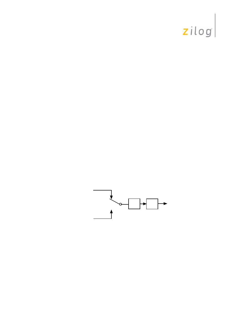
At end-of-count, the interrupt request line (IRQ4 or IRQ5), clocks a toggle flip-flop. The
output of this flip-flop drives the T
OUT
line, P36. In all cases, when the selected counter/
timer reaches its end-of-count, T
OUT
toggles to its opposite state (see
). If, for
example, the counter/timer is in CONTINUOUS COUNTING Mode, Tout has a 50 per-
cent duty cycle output. This duty cycle can easily be controlled by varying the initial val-
ues after each end-of-count.
The internal clock can be selected as output instead of T0 or T1 by setting TMR bit 7 and
bit 6 both to 1. The internal clock (XTAL frequency ÷ 2) is then directly output on P36
(see
While programmed as T
OUT
, P36 cannot be modified by a write to port register P3. How-
ever, the Z8
®
software can examine the P36 current output by reading the port register.
Figure 78. T0 and T1 Output Through T
OUT
÷
2
P36
T
OUT
TMR
D7–D6 = 01
IRQ
4
(T0 End-of-Count)
IRQ
5
(T1 End-of-Count)
TMR
D7–D6 = 10
- Z86233 Z86243 Z86733 Z86743 Z86C02 Z86C04 Z86C08 Z86C15 Z86C21 Z86C30 Z86C31 Z86C33 Z86C36 Z86C40 Z86C43 Z86C61 Z86C62 Z86C63 Z86C65 Z86C83 Z86C90 Z86C91 Z86C93 Z86C96 Z86E02 Z86E03 Z86E04 Z86E06 Z86E07 Z86E08 Z86E15 Z86E21 Z86E30 Z86E31 Z86E33 Z86E34 Z86E40 Z86E43 Z86E44 Z86E61 Z86E63 Z86E83 Z86K15 Z86L02 Z86L04 Z86L08 Z86L16 Z8E000 Z8E001 Z8PE003