Counters and timers, Cpu user manual – Zilog Z86193 User Manual
Page 87
Z8
®
CPU
User Manual
UM001604-0108
Counters and Timers
80
Counters and Timers
Z8
®
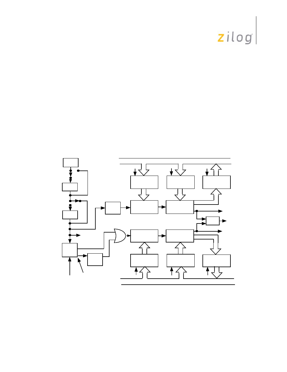
CPU provides up to two 8-bit counter/timers, T0 and T1, each driven by its own 6-bit
prescaler, PRE0 and PRE1 (see
). Both counter/timers are independent of the
processor instruction sequence, that relieves software from time-critical operations such as
interval timing or event counting. Some MCUs offer clock scaling using the SMR. Refer
to the device product specification for clock available options.
Each counter/timer operates in either Single-Pass or Continuous mode. At the end-of-
count, counting either stops or the initial value is reloaded and counting continues. Under
software control, new values are loaded immediately or when the end-of-count is reached.
Software also controls the counting mode, how a counter/timer is started or stopped, and
its use of I/O lines. Both the counter and prescaler registers can be altered while the
counter/timer is running.
Counter/timers 0 and 1 are driven by a timer clock generated by dividing the internal clock
by four. The divide-by-four stage, the 6-bit prescaler, and the 8-bit counter/timer form a
synchronous 16-bit divide chain. Counter/timer 1 can also be driven by an external input
Figure 68. Counter/Timer Block Diagram
÷
2
OSC
D1 (SMR)
÷
16
D0 (SMR)
Clock
÷
4
Logic
Internal
Clock
External Clock
Internal Clock
Gated Clock
Triggered Clock
T
IN
P31
÷
4
6-Bit
Down
Counter
8-Bit
Down
Counter
PRE1
Initial Value
Register
T1
Initial Value
Register
T1
Current Value
Register
Write
Read
Write
Write
Read
Write
6-Bit
Down
Counter
8-Bit
Down
Counter
PRE0
Initial Value
Register
T0
Initial Value
Register
T0
Current Value
Register
÷
2
Internal Data Bus
Internal Data Bus
T
OUT
IRQ
4
P36
IRQ
5
- Z86233 Z86243 Z86733 Z86743 Z86C02 Z86C04 Z86C08 Z86C15 Z86C21 Z86C30 Z86C31 Z86C33 Z86C36 Z86C40 Z86C43 Z86C61 Z86C62 Z86C63 Z86C65 Z86C83 Z86C90 Z86C91 Z86C93 Z86C96 Z86E02 Z86E03 Z86E04 Z86E06 Z86E07 Z86E08 Z86E15 Z86E21 Z86E30 Z86E31 Z86E33 Z86E34 Z86E40 Z86E43 Z86E44 Z86E61 Z86E63 Z86E83 Z86K15 Z86L02 Z86L04 Z86L08 Z86L16 Z8E000 Z8E001 Z8PE003