Handshake operations – Zilog Z86193 User Manual
Page 58
Z8
®
CPU
User Manual
UM001604-0108
Input/Output Ports
51
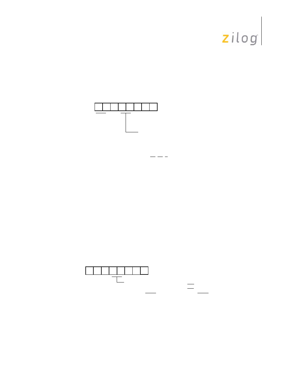
Using the Port 0–1 Mode Register, Port 1 is configured as an output port by setting bits D4
and D3 to 0, or as an input port by setting D4 to 0 and D3 to 1 (see
).
Handshake Operations
When used as an I/O port, Port 1 can be placed under handshake control by programming
the Port 3 Mode register bits D4 and D3 both to 1. In this configuration, handshake control
lines are DAV1 (P33) and RDY1 (P34) when Port 1 is an input port, or RDY1 (P33) and
DAV1 (P34) when Port 1 is an output port. See
through
Handshake direction is determined by the configuration (input and output) assigned to
Port 1. For example, if Port 1 is an output port then handshake is defined as output.
Figure 36. Port 1 I/O Operation
Figure 37. Handshake Operation
D4 D3
(F8, Write-Only)
Port 0–1 Mode Register
R248 P01M
01 = Byte Output
10 = AD0-AD7
00 = Byte Output
P10–P13 Mode
AS, DS, R/W,
11 = High Impedance AD0–AD7,
A8–A11, A12–A15
D4 D3
(F7, Write-Only)
00 P33 = Input P34 = Output
01 P33 = Input P34 = DM
Port 3 Mode Register
R247 P3M
10 P33 = Input P34 = DM
11 P33 = DAV1/RDY1 P34 = RDY1/DAV1
- Z86233 Z86243 Z86733 Z86743 Z86C02 Z86C04 Z86C08 Z86C15 Z86C21 Z86C30 Z86C31 Z86C33 Z86C36 Z86C40 Z86C43 Z86C61 Z86C62 Z86C63 Z86C65 Z86C83 Z86C90 Z86C91 Z86C93 Z86C96 Z86E02 Z86E03 Z86E04 Z86E06 Z86E07 Z86E08 Z86E15 Z86E21 Z86E30 Z86E31 Z86E33 Z86E34 Z86E40 Z86E43 Z86E44 Z86E61 Z86E63 Z86E83 Z86K15 Z86L02 Z86L04 Z86L08 Z86L16 Z8E000 Z8E001 Z8PE003