Additional information, Document revision history – Altera Stratix IV GX FPGA Development Board User Manual
Page 79
August 2012
Altera Corporation
Stratix IV GX FPGA Development Board
Reference Manual
Additional Information
This chapter provides additional information about the document and Altera.
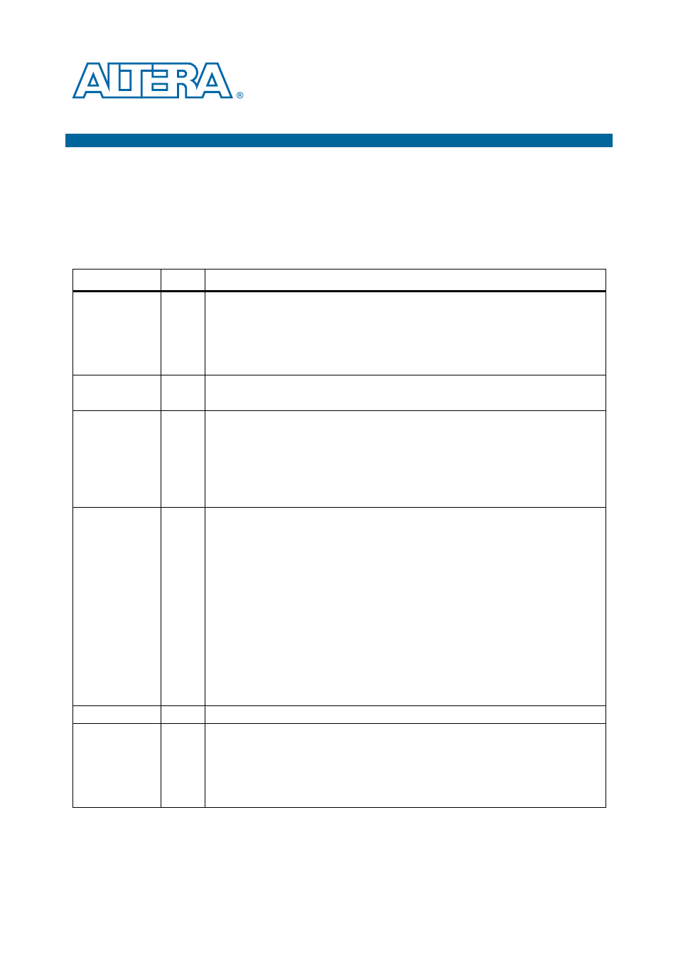
Document Revision History
The following table shows the revision history for this document.
Date
Version
Changes
August 2012
2.3
■
Corrected the schematic signal names for board references J2.108 and J2.109 in
■
Added DDR3BOT_RSTn signal in
.
■
Added DDR3TOP_RSTn signal in
.
■
Maintenance release.
August 2010
2.2
■
Updated the manufacturing part number of the flash device in
■
Converted document to new frame template and made textual and style changes.
June 2010
2.1
■
Updated Stratix IV GX FPGA development board block diagram in
.
■
Updated the description of the HDMI video port (J11) in
■
Updated the manufacturing part number of the Stratix IV GX device in
.
■
Added
“Single-Die Flash Version Differences” on page A–1
to document the replacement
of dual-die 512-Mb flash with a single-die flash device.
November 2009
2.0
■
Updated MAX II CPLD EPM2210 System Controller block diagram in
■
Added two I/O signals, CLK100_SDA and CLK100_SCL in
.
■
Replaced 100-MHz fixed frequency oscillator (X6) with a programmable oscillator
described in clocking section.
■
Increased SRAM frequency to 250 MHz.
■
Corrected schematic signal names in
and
■
Added manufacturing information for QDRII+ top port 1 SRAM memory in
and
.
■
Updated voltage values for the power rails measurement in
■
Updated power distribution system in
■
Added an appendix to document the board revision change (engineering silicon to
production silicon revisions).
August 2009
1.3
■
Corrected DDR3 top port schematic signal names in
July 2009
1.2
■
Added HSMA present LED and HSMB present LED board components, and corrected
SSRAM x36 Memory description in
.
■
■
Corrected PCI Express edge description in
■
Corrected LVDS schematic signal names in
.