Table a–2 – Altera Stratix IV GX FPGA Development Board User Manual
Page 76
A–2
Appendix A: Board Revision History
Engineering Silicon Version Differences
Stratix IV GX FPGA Development Board
August 2012
Altera Corporation
Reference Manual
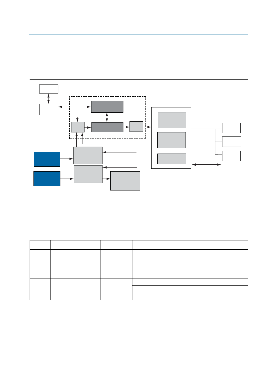
illustrates the Max II CPLD EPM2210 System Controller block diagram
whose functionality and external circuit connections on the engineering silicon board
differ from the production silicon board.
shows the production
silicon MAX II CPLD EPM2210 System Controller block diagram.
lists information for the targeted power rails whose voltage values on the
engineering silicon board differ from the production silicon board.
shows the production silicon voltage values.
The engineering silicon version does not have the programmable oscillator supported
for reference designator X6 but has a fixed frequency 100-MHz oscillator from Epson.
The engineering silicon board version works with the new programmable oscillator if
you remove the Epson device and install it. The latest MAX
II CPLD EPM2210 System
Controller also works with older board versions.
Figure A–1. MAX II CPLD EPM2210 System Controller Block Diagram
MAX1619
Controller
Information
Register
EMB
Blaster
MAX II Device
Power
Calculation
SLD-HUB
PFL
FSM BUS
Power
Measure
Results
Virtual-JTAG
PC
Temperature
Measure
Results
FPGA
LTC2418
Controller
FLASH
Decoder
Encoder
GPIO
JTAG Control
SRAM
Control
Register
Table A–2. Power Rail Measurements that Differ on the Engineering Silicon Board
Switch
Schematic Signal Name
Voltage (V)
Device Pin
Description
1
S4VCC
0.95
VCC
FPGA core and periphery power
VCCHIP
PCI Express hard IP block
7
S4VCCD_PLL
0.95
VCCD_PLL
PLL digital
8
S4VCCA_GXB
3.3
VCCA
XCVR analog TX/RX driver (mA only)
E
S4VCC_GXB
1.2
VCCR
XCVR analog receive
VCCT
XCVR analog transmit
VCCL_GXB
XCVR clock distribution