User-defined leds, General user-defined leds, User-defined leds –28 – Altera Stratix IV GX FPGA Development Board User Manual
Page 36: General user-defined leds –28
2–28
Chapter 2: Board Components
General User Input/Output
Stratix IV GX FPGA Development Board
August 2012
Altera Corporation
Reference Manual
lists the user-defined DIP switch component reference and the
manufacturing information.
User-Defined LEDs
The development board includes general and HSMC user-defined LEDs. This section
describes all user-defined LEDs. For information on board specific or status LEDs,
refer to
“Status Elements” on page 2–17
.
General User-Defined LEDs
Board references D6 through D13 and D16 through D23 are 16 user LEDs that allow
status and debugging signals to be driven to the LEDs from the designs loaded into
the Stratix IV GX device. The LEDs illuminate when a logic 0 is driven, and turns off
when a logic 1 is driven. There is no board-specific function for these LEDs.
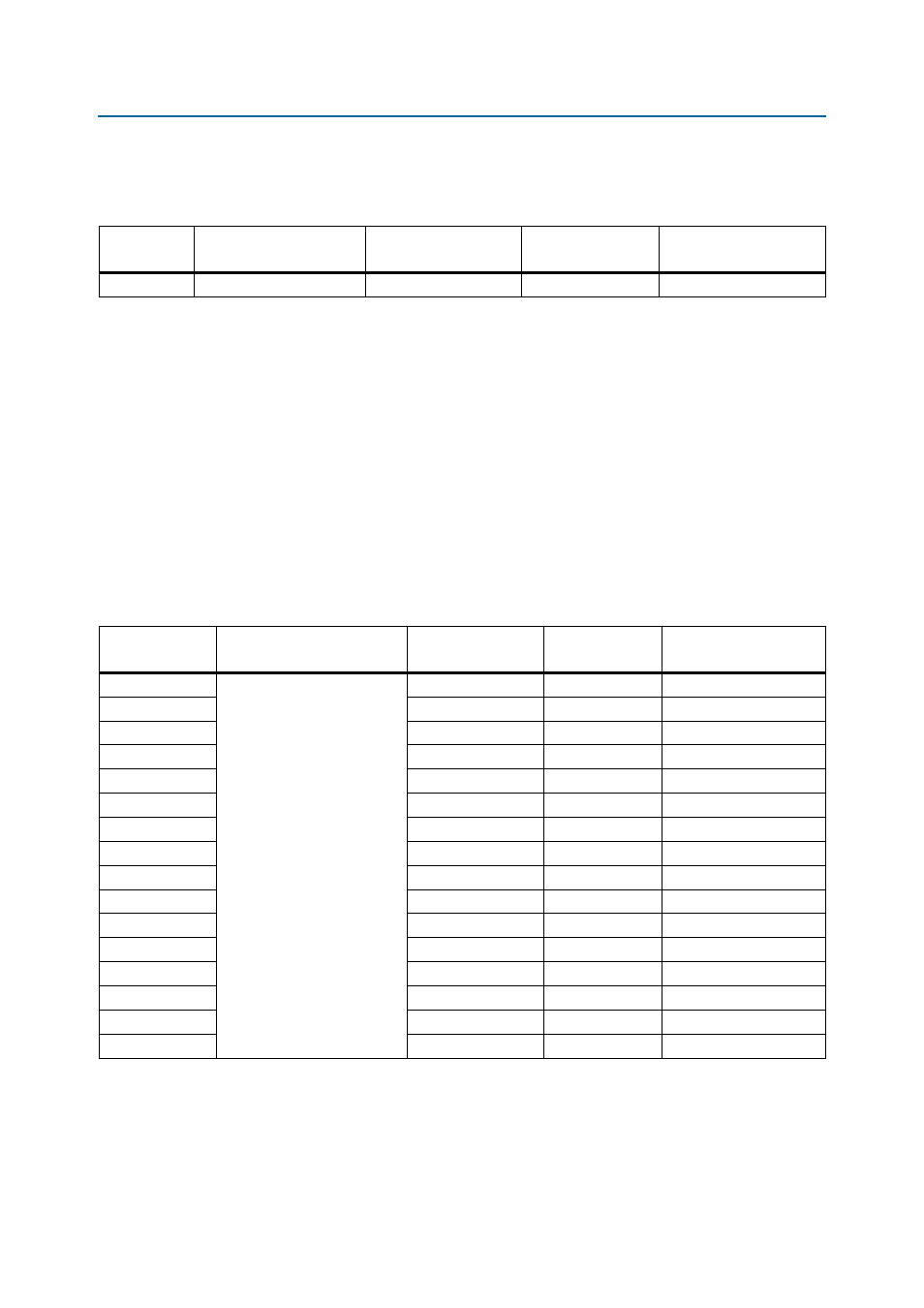
lists the user-defined LED schematic signal names and their corresponding
Stratix IV GX pin numbers.
Table 2–26. User-Defined DIP Switch Component Reference and Manufacturing Information
Board
Reference
Description
Manufacturer
Manufacturer
Part Number
Manufacturer Website
SW3
Eight-position DIP switch
C & K Components
TDA08H0SB1
Table 2–27. User-Defined LED Schematic Signal Names and Functions
Board Reference
Description
Schematic
Signal Name
I/O Standard
Stratix IV GX Device
Pin Number
D23
User-defined LEDs.
Driving a logic 0 on the I/O
port turns the LED ON. Driving
a logic 1 on the I/O port turns
the LED OFF.
USR_LED0
2.5-V
F33
D22
USR_LED1
2.5-V
AK33
D21
USR_LED2
2.5-V
W28
D20
USR_LED3
2.5-V
L34
D19
USR_LED4
2.5-V
AM34
D18
USR_LED5
2.5-V
M32
D17
USR_LED6
2.5-V
L35
D16
USR_LED7
2.5-V
AM35
D13
USR_LED8
2.5-V
N34
D12
USR_LED9
2.5-V
W35
D11
USR_LED10
2.5-V
AE30
D10
USR_LED11
2.5-V
V30
D9
USR_LED12
2.5-V
AG30
D8
USR_LED13
2.5-V
AD29
D7
USR_LED14
2.5-V
U31
D6
USR_LED15
2.5-V
U35